*
Numerical Modelling of Kennebecasis Bay

Susan  Haigh and John Hughes Clarke


Please note that this web page is currently under development

Area of Study:

The Saint John River is roughly 700km long and flows through the Provinces of New Brunswick and Quebec and the State of Main.  It flows from its source in the Saint John Pond, Maine and discharges into the the Bay of Fundy at the city of Saint John, New Brunswick.  The Bay of Fundy is known for having the highest tides in the world with extreme tidal ranges of up to 16m.  Tides in the Saint John River Estuary are damped by the Reversing Falls and have a range of about 50cm.  We model the Saint John River from Brandy Point to just above the Reversing Falls.  This includes the Kennebecasis Estuary which is a fjord-like basin that lies off the main St. John River system. The Kennebecasis lies parallel to Long Reach.  Unlike Long Reach, through which the main St. John river flows, the Kennebecasis has almost no fresh water flux. The Hampton river at its NE end provides only a minor inflow.  Kennebecasis Bay has a 5-10m layer of fresh water overlying a salt layer.  There is a sill between the river and the fjord where the depth drops from ~10m to +30m.  Water in Kennebecasis Bay is fairly stagnant although salt water can spill over the sill during the flood tide if the conditions are correct.


Observations:

Historical Data:

Trites(1960) conducted a survey of Kennebecasis Bay and the Saint John estuarial system.  There were four seasonal surveys which took place in 1957 and 1958.  The summer survey took place from 24-26 August 1957 and is closest to the time of year which we are modelling.  In Kennebecasis Bay, the deep water has a temperature of 4.8°C and salinity of 21.8ppt.  The surface water is warmer fresher at  18.5°C to 19.5°C and 8ppt to 11ppt.   Trites(1960) observed that during the summer survey new water was moving into Kennebecasis Bay.  He noted that the water was moving over the sill and down towards the bottom.  Trites(1960) also had stations in the Saint John River.

July 2001 Survey:

Our model has two open boundaries.  The upstream boundary is located at Brandy Point (refered to as Brandy) where the river is roughly 900m wide.  The downstream boundary is located at the beginning of the gorge which leads to the Reversing Falls (called Gorge).  Here the River has begun to constrict and is approximately 350m wide.   On July 21, 2001(Gorge) and July 23, 2001(Brandy) the Ocean Mapping Group acquired data at the two boundaries using the UNB research vessel Mary-O.  Observations were taken over a tidal cycle (12.42 hours).  At each boundary, the vessel started at the western shore, steamed across the boundary taking ADCP (acoustic doppler current profiler) measurements.  When the vessel reached the eastern shore, it turned around and returned to the western shore, stopping in the middle of the river to take a CTD (conductivity, temperature, depth) profile.  This loop was repeated for the duration of a complete tidal cycle.  RTK measurements were taken continuously throughout the entire tidal cycle.

Surface Elevation:
Surface elevation is obtained from the RTK data.  There are two issues to consider when processing the RTK data.  The first is that RTK data measures the sea surface elevation from the ellipsoid whereas we require the elevation from the geoid.  As the distance between the ellipsoid and the geoid is a function of  location, this has to be taken into account.  At Brandy, the ellipsoid is 21.651m above the geoid.  At Gorge, the ellispoid is 21.581m above the geoid.  These distances need to be added to the measured RTK elevation to find the elevation from the geoid.  The second issue is that the measured RTK data is quite noisy and a smoother profile is required to force the numerical model.  

The processed elevation data is shown in Figure 2.  Zero phase is arbitrarily set to 8:20GMT on 21 July 2001.  The M2 residual elevations at Brandy is 4.8cm higher than the M2 residual elevation at Gorge.    This implies a net downstream flow from Brandy to Gorge which is as expected.  The M2 amplitude and phase are 23.8cm and 284.6° at Brandy and 21.2cm and 268.3° at Gorge.  The M2 tide signal at Brandy lags that at Gorge by 34 minutes but the tides are not symmetric.   Figure 2 shows that high tide at Brandy lags high tide at Gorge by only 8 minutes whereas low tide at Brandy lags low tide at Gorge by 51 minutes.

Figure 2: Measured elevation at the boundaries

Normal Velocity:

The velocity profiles at the open boundaries were measured using an ADCP.  The amount of data acquired is significant and needed processing to be manageable.  The ADCP sends out a ping at a time interval of less than one second and measures the velocity in 1m bins.  It also measures the distance to the sea bed.  The ADCP transducers are mounted to the bottom of the boat, one meter below the sea surface.  In addition, the ADCP does not measure the velocity for the first 1.61m of the water column.  This means that the first velocity measurement is at 2.61m below the sea surface.  We assume that the velocity is constant in the top 2.61m of surface water.  At the bottom of the water column, there is a layer at the sea bed where the ADCP cannot measure the velocity.  The thickness of this layer depends on the angles at which the transducers are mounted.  On the Mary-O, the transducers are mounted at a 20° angle.  The range of acceptable data is Dcos20°=.94D where D is the distance from the ADCP to the bottom (reference?).  For simplicity, we assume that the velocity is constant below the range of acceptable data and ignore boundary layer effects.

There are 46 tracks across the Brandy boundary (59 for Gorge).  Each Transect has between 331 and 614 pings (104 and 182 for Gorge).  Our aim was to reduce the amount of data and make it usable with the QUODDY model.  Firstly we removed spikes and then ensemble averaged using the data from 5 pings.  We used the mean position, the median depth and average the velocity in each bin.

Since, for each transect, the time between the first and last pings was at most 0.7% (0.53% for Groge) of the total tidal cycle we have assumed that transects are stationary.  This allows us to determine the elevation for each transect using the data from Figure 2.  By projecting the ensemble averaged data onto the Brandy boundary and removing the elevation, we have the depth of the cross-section of the Saint John River at Brandy.  As we have 46 cross-sectional depth profiles, we average these to determine the depth at the boundary.  This final depth profile was used to compute the depth at the boundary nodes of the QUODDY grid.  Upon examination of the processed ADCP data, we observe that boundary effects are present along the sides and bottom of the river cross-sections.  Otherwise, there is not a lot of crosswise variation in the velocity structure.  We feel that using a velocity field that varies vertically but not cross-wise is a reasonable representation  of the cross-stream velocity.  At present, we use a velocity profile that is averaged over the middle third of the cross-section across the river.

Temperature and Salinity:

There are a total of 39 CTD casts at Brandy and 57 CTD casts at Gorge.  When available, only the downward casts were used as the CTD probe caused disturbances in the water column during its ascent to the surface.  There was a bias in the salinity data that was removed by subtracting 5ppt from the measured value.  Spikes were removed from the data which was subsequently smoothed.  Finally, the data was interpolated onto a regular vertical grid with 1m spacing (0-17m for Brandy and 0-27m for Gorge).

Time series of measered temperature, salinity, and normal velocity  profiles at Brandy and Gorge are shown in Figures 3 and 4.  During the ebb tide, the river is flowing downstream at both boundaries, with a much stronger flow at Gorge.  Gorge is located at the constriction of the Saint John River just above the Reversing Falls.  As the river width is narrower at Gorger than at Brandy, it is expected that the velocity magnitude be greater at Gorge.  During the ebb tide there is a fresh, warm layer of water which originated from the Saint John River lying over a salty, cooler layer of water.  The lower layer is a combination of water from the Saint John River and the Bay of Fundy which has been well mixed in the Reversing Falls.  During the flood tide, the currents at both boundaries are reversed, heading upstream.  At Brandy the temperature and salinity structures do not change significantly throughout the tidal cycle.  At Gorge, there is an influx of cooler, salty water from the Reversing Falls and the fresh water layer disappears briefly at high tide.


Figure 3: Measured elevation, temperature, salinity and normal velocity at the Brandy boundary.


Figure 4: Measured elevation, temperature, salinity and normal velocity at hte Gorge Boundary.

June 2003 Survey:

On 13 June 2003, the Ocean Mapping Group conducted a survey between the Saint John River and Kennebecasis Bay.   The survey took place over an entire tidal cycle.  A typical transect is shown in Figure 5.  During this survey, temperature and salinity profiles were measured using a towed CTD (EXACT DESCRIPTION NEEDED).  Temperature and salinity data was processed as described above for Brandy and Gorge.  The measurements of this survey are important to this numerical  study for two reasons.  First, since measurements were taken over an entire tidal cycle, we are able to see the effects of the tide at the mouth of Kennebecasis Bay.  This allows us to examine how well our model is performing in this area.  Second, this survey provides us with data with which to initialize our model.


Figure 5: Observations made from Saint John River into Kennebecasis Bay on 13 June 2003

Kennebecasis Bay has a permanent pycnocline.  The temperature and salinity of the deep water remain at approximatly 4.9°C and 21.8ppt, respectively.  The location of the pycnocline moves up and down throughout the tidal cycle, rising to a minimum depth of approximately 9m at the midpoint of the ebb tide and reaching a maximum depth of approximatly 15m at the midpoint of the flood tide.  There is also an internal wave at the density interface which appears to be triggered by water spilling over the sill into Kennebecasis Bay during high tide.  This is shown in Figure 5.  Here we see the formation of the wave which then travels along the density interface into Kennebecasis Bay.  Of interest is the temperature and salinity of the injected water.  It has the same temperature and salinity of the water that occurs at the density interface.  This is in contrast to what was observed by Trites(1960) where the new water entering Kennebecasis Bay moved over the sill and towards the bottom, implying that it was saltier and colder.

Surface temperatures and salinity in Kennebecasis Bay vary slightly over the tidal cycle with ranges from 15.5°C to 16.5°C and 2.0ppt to 2.4ppt, respectively.  This is cooler and less saline than the surface waters in Kennebecasis Bay observed by Trites.  The difference in surface temperature and salinity can be accounted for as Trites(1960) data was collected later in the summer.  As the summer progresses the surface waters are heated.  Also, they become more saline due to evaporation.  (IS THIS TRUE?) 

The Numerical Model:

We are using the three-dimensional finite element shelf circulation model QUODDY, version 5_1.0 to model the Kennebecasis Estuary.  For a description
of the model, we refer you to Lynch et al. 1995.  QUODDY is a nonlinear, free-surface, tide-resolving model.  It uses a general terrain-following vertical coordinate (sigma-coordinate) which provides tracking of the free surface.  QUODDY is driven by rotation, tide, wind, and barotropic and baroclinic pressure gradients.  For the present study, the effects of wind are ignored.

Finite Element Grid:

A triangular grid was generated using BatTri, a Matlab interface to the finite element grid generator Triangle.  The model's bathymetry was computed by interpolating bathymetric data from Canadian Hydrographic Service (CHS) Chart 4141.  The model's coastline was created from the 2m contour line in the river portion of the model and from the 15m contour in Kennebecasis Bay.  Different contours were chosen in the two regions as Kennebecasis Bay has a very steep coastline and the two contours almost coincide in this area.  The deeper contour was chosen as sigma coordinate models perform better if the change in depth over an element is minimized.  The current grid has 5375 nodes and 9674 elements.  The two-dimenstional elements range in size from 814m2 to 24,013m2.  In the vertical 21 levels are used.  From the surface down to 15m of depth they are equally spaced at intervals of 1m.  The remaining 5 layers are equally spaced amoung the remaining depth.  If the depth is less than 20m, then all 21 layers are equally spaced throughout the entire water column.  This vertical grid was chosen to resolve the pycnocline in Kennebecasis Bay.

Model Boundary Conditions:

The two open boundaries are forced as follows.  At each time step, the elevation is specified using the observed values described above.  QUODDY calculates the resulting velocity, temperature and salinity fields, Vq, Tq, and Sq, respectively.  Before proceeding to the next time step, we adjust the computed velocity, temperature and salinity fields by relaxing towards the observed velocities, temperature, and salinity fields at each of the boundaries: Vo, To, and So, respectively.  The final predicted velocity, temperature and salinity are given by:
F=e-dt/tau Fq+ (1-e-dt/tau) FoHOW DO I DO GREEK SYMBOLS?

where F is the calculated field, dt is the time step and tau is the relaxation time.  For the run described here, we use a relaxation time of 5 minutes.

It should be noted that at each boundary we have assumed that there is no cross-stream variation in the elevation.  This is not entirely true as there is a slope in the sea-surface elevation in the cross-stream direction which is due to the Coriolis force.  Using a constant cross-stream elevation is a reasonable approximation as the change in elevation over a tidal cycle is much greater than the cross-stream variation which results from the Coriolis force.

Initial Temperature and Salinity:

We have attempted to initialize the temperature and salinity fields with profiles that are as realistic as possible given the limitied data available.  Properly initializing the temperature and salinity profiles is particularly important in Kennebecasis Bay as there is very little water movement in the bay itself.  In the Saint John River portion of the model the effects of the tides are strong and it is felt that accurate initial conditions are not as crucial since any errors would be quickly be advected out of the domain.

The model is initialized with data from the 13 June 2003 survey.  We start the model at 250° phase in the tide just before high tide at Gorge.  The transect which starts in the Saint John River at tidal phase 240.95° and ends in Kennebecasis Bay at 256.06° is used.  The data of the June 2003 are projected onto a line which runs from the Saint John River into Kennebecasis Bay.   To determine the initial vertical temperature and salinity profile at a given node in the grid, we project that node onto the same line and then interpolate from the observed values.  If the projected node lies to the West of the most westward projected observation we use the temperature and salinity profiles of that most Westward observation and likewise at the Eastern end.


Results:

We are running QUODDY in the baroclinic mode.  
The model starts at rest with zero elevation everywhere.  The elevation and normal velocities are slowly ramped up over the first tidal cycle.  We run the model for a total of six tidal cycles and examine the results.   There are two areas in which we are interested : the Saint John River portion of the model and the entrance to Kennebecasis Bay.

First we examine the Saint John River portion of the model. 
The dynamics of the Saint John River are controlled by the forcing at the open boundaries Brandy and Gorge.   Thus it is important to know how well the model reproduces the boundary conditions at the two open boundaries.  As we are relaxing towards temperature, salinity and normal velocity at the boundary, we expect the model to reproduce the measured values reasonably well.  Figures 6 and 7 show the modelled elevation, temperature, salinity and normal velocity at the Brandy and Gorge boundaries respectively.  Comparing these with the measures values in Figures 3 and 4 we notice that the model predicts reasonable temperature and salinity structures when water is flowing into the domain which occurs during the ebb tide at Brandy and the flood tide at Gorge.   It is of interest to note that at both Brandy and Gorge, the bottom salty water in the model is less salty than those observed.  There are also differences in temperatures.     When water is flowing out of the model boundary during the flood tide at Brandy and the ebb tide at Gorge, temperature and salinity structures are more influenced by the modelled temperature and salinity inside the model domain and do not match the observed values as well.  In particular, the lower salty layer at Gorge almost dissappears during the ebb tide.
Normal velocities are reproduced reasonable well in terms of direction and timing throughout the tidal cycle.  At Gorge, the amplitudes of the velocity are less at all phases of tidal cycle.  At Brandy, the upstream flow during the flood tide is stronger in the model than observed.


Figure 6:  Modelled elevation, temperature, salinity and normal velocity at the Brandy boundary.   Results are for node 4060 in the center of the Brandy boundary (see Figure for location).


Figure 7:  Modelled elevation, temperature, salinity and normal velocity at the Gorge boundary.  Results are for node 5014 in the center of the Gorge boundary (see Figure for location).

The differences in the modelled and observed temperature and salinity mentioned above lead us to question how well the model conserves the total salt and heat.  Ideally, over a tidal cycle, the total heat/salt flux at Brandy would equal the total heat/salt flux at Gorge.  Approximate total heat and salt flux at the Brandy and Gorge boundaries are computed for the last four tidal cycles of our simulation and are given in Table 1.   These flux are calculated by integrating the heat/salt flux, T/S*vn, over the cross-sectional area of the boundary and then integrating this over an entire tidal cycle.  The normal velocity, vn, is defined as being positive downstream.  Thus a positive/negative flux at Brandy means that there is a net gain/loss of heat/salt.  A positive/negative flux at Gorge means that there is a net loss/gain of heat/salt.  The values in Table 1 show that both fluxes at Brandy and Gorge are contributing to a net decline in temperature and salinity of our model domain.


Tidal Cycle
Total T Flux
Brandy
Total T Flux
Gorge
Total S Flux
Brandy
Total S Flux
Gorge
3
-2.3e7
1.5e8
-4.0e6
6.8e6
4
-2.1e7
1.5e8
-3.9e6
6.9e6
5
-1.9e7
1.6e8
-3.8e6
7.1e6
6
-2.2e7
1.6e8
-4.0e6
7.0e6
Table 1:

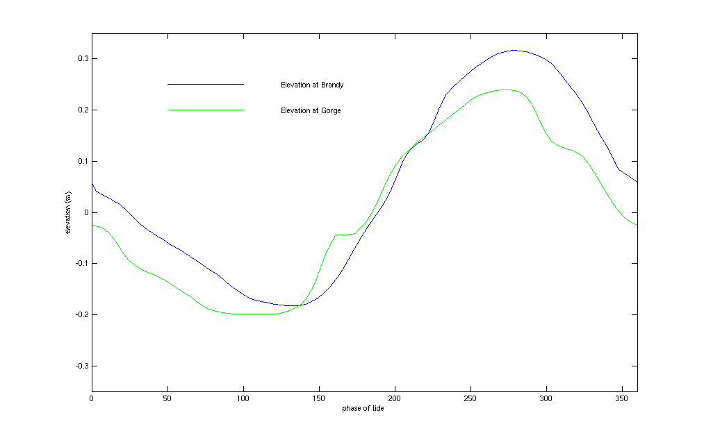
Next we examine how the model behaves in the interior of the model domain.  We know that there is residual downstream flow from Brandy to Gorge.  We expect the model to reproduce this residual flow as the elevations used to force the boundaries have residuals of 4.8cm at Brandy and 0cm at Gorge.  Figures 8 and 9 show the M2 residual elevation and the vertically averaged residual velocity fields.   These show a decrease in the elevation from Brandy to Gorge and a net downstream flow.


Figure 8: M2 residual fields

The flow in the Saint John River portion of the model is a balance between the river's fresh water discharge and the salt water brought in from the Bay of Fundy by the tides.   Although there is a net downstream flow due to the river's discharge into the Bay of Fundy, the tide affects the direction of the instantaneous flow as well as the water properties.  It is useful to explain the flow in terms of the actions of the tide at Gorge.  During the flood tide, cold salty water from the Reversing Falls enters the Saint John River at Gorge.  This pushes the water upstream causing a reversal in the rivers flow.  As high tide approaches, the river 's velocity slows downs and then does an about turnjust after high tide.   Figures 6 and 7 indicate that the normal velocity at Gorge reverses before that at Brandy indicating that, as the tide receeds, water is being  sucked out of the Saint John River into the Bay of Funday.     At low tide, the flow is dominated by the river's fresh water discharge.  At Brandy, there is a permant two layer density structure with fresh warm water lying over cool salty water.  To illustrate how the model is performing in the Saint John River, we have chosen to examine a transect from Brandy to Gorge.  Figure 10 shows the instantaneuos behaviour of the model along a transect from Brandy to Gorge during the flood tide just before high tide.  At this point, the water is flowing upstream and cold salty water from the Reversing Falls is still entering the Saint John River system at Gorge.  We observe that the cool salty water flowing upstream from Gorge doesn't protrude far enough upstream to join with the cool salty water on the Brandy side.  In fact these two water segments always remain detached.  At first we thought that this was a problem with the model but observations made on JOHN DATE AND PICTURE PLEASE and shown in Figure 11 show that this is indeed what happens.  This indicates that the cold salty water at Brandy does not get renewed each tidal cycle but depends on the strength of the tides and the river runoff.


Figure 10: Instantaneous flow along a transect in the Saint John River from Brandy to Gorge.  The transect is indicated by the black line in the vertically averaged velocity field figure.  For plots of temperature, saliity, and tangential velocity, Brandy is located at the left end and Gorge at the right.  The * on the Brandy boundary is node 4060 and the  * on the Gorge boundary is node 5014.

*************JOHN FIGURE PLEASE*************

Figure 11: 

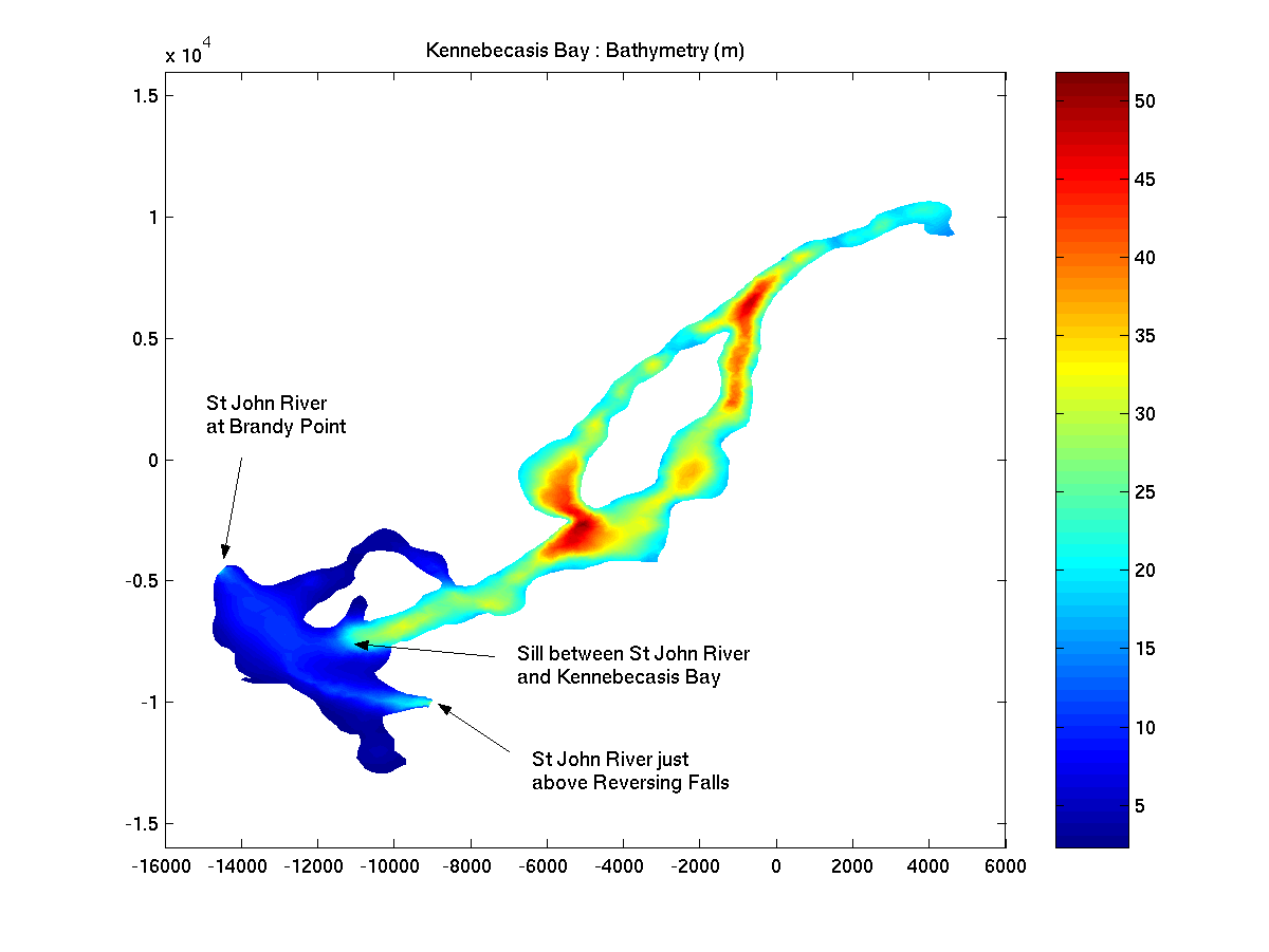
Finally we examine the flow from the Saint John River into Kennebecasis Bay.  Kennebecasis Bay is a fjord-like estuary.  It is deep (up to 60m deep in spots) and has a permanent pycnocline with warm fresh water lying over cold salty water.  The water in Kennebecasis Bay has very little movement although we know from Trites (1960) and from the 13 June 2003 survey that water can be injected into Kennebecasis Bay from the Saint John River at high tide.  Figure 12 shows the instantaneous flow in Kennebecasis Bay along a transect from the Saint John River into the bay.  The flow is shown at the beginning of the ebb tide when the water in the Saint John River is flowing downstream.  This corresponds to the same phase of the tidal cycle shown in Figure 5.  Comparing figures 5 and 12 the first thing that we notice is that the observed temperature and salinity is cooler and saltier than the modelled temperature and salinity.  NEED TO TIE THIS IN TO SALT AND HEAT BUDGET. Anotherdifference worth noting is that the modelled pycnocline is significantly thicker than the measured pycnocline.  This is likely due to the diffusion coefficient used by the numerical model being larger than the actual physical diffusion in Kennebecasis Bay.  As there is little water movement in Kennebecasis Bay, the vertical mixing of temperature and salinity is determined by the diffusitiy of these agents.  In pure water the diffusivity of heat and salt (.01 molar) at 15°C is 14x10-8m2/s (Fischer et al., 1979) and 0.1493x10⁻⁸m2/s (CRC Handbook of Chemistry and Physis), respectively.  In QUODDY, we set the minimum vertical eddy diffusivity for heat and salt to 10-4m2/s.  This larger diffusivity value is required for numerical stability (CHECK THIS) but has the dissadvantage of predicting more vertical diffusion than is actually present.  In areas where the flow is dominated by the tide, this effect is not as noticeable.

One feature of the numerical model is that it predicts a flow in Kennebecasis Bay itself.  Figure 12 shows that there is a flow into Kennebecasis Bay in the surface waters and a return flow in the bottom waters.  We know that this flow is a numerical artifact.  After some investigation we believe that this flow is due to an error in the calculation of the baroclinic pressure gradient in sigma coordinates when there is a sudden change in topography.


Figure 12:  Instantaneous flow along a transect from the Saint John River into Kennebecasis Bay.  The transect is indicated by the black line in the vertically averaged velocity field figure and follows the transect of the 13 June 2003 survey (see Figure 5).  For plots of temperature, saliity, and tangential velocity, the Saint John River  is located at the left end and Kennebecasis Bay at the right.  The   *, *, and * in the vertically averaged velocity field indicate the locations at which the elevation is shown.


  1. flow depends on river runoff (time of year) and tidal elevation (phase of tide)
  1. Kennebecasis Bay is a stratified fjord type estuary with very little water movement within the bay itself
  2. Depending on the time of year, water from the Saint John River can spill over the sill into Kennebecasis Bay
We compare the model results with observations to see how well the model reproduces the flow in the river system.
References:

Fisher, H.G., List, E.J., Koh, R.C.Y., Imberger, J., and Brooks, N.H.  1979.  Mixing in Inland and Coastal Waters, Academic Press Inc., San Diego, WA, USA.

Haney, R.L. 1991. On the Pressure Gradient Force over Steep Topography in Sigma Coordinate Ocean Models. J. Phys. Oceanogr, 21: 610-619.

Trites, R.W. 1960. An Oceanographical and Biological Reconnaissance of Kennebecasis Bay and the Saint John River Estuary.  J. Fish Res. Bd. Canada, 17(3): 377-408.

Weast, R.C. ed.  1988.  CRC Handbook of Chemistry and Physics, 1st student ed., CRC Press Inc., Baco Raton, FL, USA.