 |
GGE 3353 -
Imaging and Mapping II :
Submarine Acoustic Imaging Methods Instructors : John E. Hughes Clarke Fall Term (September - December 2010) Monday - Wednesday - Friday 1330 -1420 E4 (last updated September 2010) |
| |
GGE 3353 -
Imaging and Mapping II :
Submarine Acoustic Imaging Methods Instructors : John E. Hughes Clarke Fall Term (September - December 2010) Monday - Wednesday - Friday 1330 -1420 E4 (last updated September 2010) |
To ensure that the students have covered the minimum material requirements embedded in the Canadian Land Surveyors (CLS) accreditation.
(2) : to appreciate the similarities and differences between submerged acoustic imaging techniques and atmospheric electromagnetic imaging.
(3) : to be able to design the most effective submarine survey given specific clients needs
(4) : to be knowledgeable about currently available, state-of-the-art acoustic survey systems. Includes the theory, application and processing requirements.
Introduction - Course Overview
The outline of the course is described along with the timetable. Inter-class clashes will hopefully be resolved. The requirements for course assessment and marking will be described. Identification of the student body. The relationship of this course to:
Typical Applications of Submarine Acoustic Imaging
A series of real examples for which submarine acoustic imaging is required will be described. These will include examples from:
Physical Oceanography A - a description of the water masses and processes that drive worlds oceans
A description of the typical water masses and the processes that drive their circulation in the following environments:
Physical Oceanography B - physical properties of seawater and their effect on acoustics
Measurement of temperature, salinity, density, attenuation and sound speed . The instruments, the empirical relationships. And the effect of these physical properties on the propagation of sound in the ocean. Typical ocean wave spectra and their influence on vessel motions.
Marine Geology A - a description of the sediments that make up the floors of the Oceans
A description of the typical scales of relief and the types of seabed material type commonly found in the following submarine environments:
Marine Geology B - physical properties of marine sediments and their effect on acoustics
Measurement of :
The effect of these properties on the reflection and scattering of
sound at the sediment water interface.- Surface and Volume Scattering
Reflection and Refraction - The Critical Angle
Method for generating and sensing acoustic energy in water.
Description of acoustic signals, amplitude, frequency and phase
The choice of frequency - range issues.
Dimension and beam width - directivity (an introduction, more in
angular resolution later).
Arrays - line, disk, barrel and spherical.
Propagation and Refraction (2 lectures)
Source level , spherical (and cylindrical) spreading and
attenuation (absorption and scattering). Typical Ocean noise spectra
Harmonic Mean concept, modelling a stratified ocean.
Snells Law, approximation of a water mass by constant layers or
constant gradients.
CW Pulse and Chirp. The concept of bandwidth and its effect on range resolution. Convolution and deconvolution, Auto-Correlation. Matched Filters, extracting signal from noise. Single beam bottom de. Single beam bottom detection issues.
Angular Resolution (2 lectures)
Directionality and Beam Forming. Line and Circular arrays.
Discretely sampled apertures. The relationship between wavlength and
array dimension.
Weighting or Shading. Using the Knudsen sources as type examples.
Nearfield and farfield. Focussing.
Beam
Steering : Time, Phase and FFT methods (2 lectures)
An alternate approach to passively estimating the elevation angle
for
a given time of arrival is to actively constrain the elevation angle
within which the echo might fall. Introducing the idea of handling the
signal at each element of a line array separately. Introducing time
delays and
phase delays. FFT beam forming, looking at the instantaneous
signal
across the array - the relationship between spatial wavelength and
angle.
Why a steered beam forms a cone rather than a tilted plane.
Introduce narrow beam formation using the product of two orthogonal
line arrays - the Mills Cross.
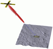
Horizontal Positioning Requirements
How accurate do we need to be? By analysing the spatial
resolution of sonar systems, the required positioning accuracy will be
assessed.
Compare these accuracies with those achievable through the "many modes
of GPS". Pointer toward GGE4042 - (go ask Dave/Marcelo).
Intro. to the ships reference frame. Intro to submerged positioning
methods, USBL, SBL, LBL, LUSBL - common achievable accuracies as
function of range and angle. Relate frequencies used back to
achievable ranges and range resolution.
Vertical Positioning Requirements - Long Period (2 lectures)
: Overview datums and enough tides to get through CCLS. Mean sealevel. Choice of low water. Tidal ranges. Driving forces behind tides. Principal tidal frequencies, their relative importance. Spectral analysis of tide time series. Prediction of tides. Typical tide measuring devices.
Vertical Positioning Requirements - Short Period
Heave Sensors and the future with RTK. The bandwidth limitation of heave sensors. Long period heave artifacts. Choice of high pass filter time constants and damping coefficients. Causal filters. Delayed heave output. The response of a heave sensors to a step function. The problem of speed, trim, loading changes. The importance of heave sensor location. Induced heave. AC and DC coupled lever arms.
Orientation (Roll, Pitch and Heading) Measurement (1 lectures)
The required accuracies needed in the three axes. The update rates needed, given typical ocean wave spectra and roll and pitch excursions. Introduction to inertial sensors (accelerations and angular rates). The vertical gyro algorithm, and limitations of the same. Use of aiding speed and heading information. Aided inertial navigation. The problem of time delays. The problem of alignment, static biases and inter-axis crosstalk.
Single Beam and Sidescan Surveying - Single Beam Method (2 lectures)
Explain the traditional model for single beam and sidescan surveying. Contrast the needs of nautical charting and engineering surveys.
Using what we now know about range and angular resolution, decide what accuracies we should achieve using a single beam as a function of : depth, bottom slope and bottom wavelengths. Describe Boom Systems, Check Lines, Interlines - Shoal Exams. Explain Bar Checks, use of harmonic sound speed, integration of heave sensors. Phasing, sweep rates, range settings. First introduction to the application of heave, draft , lever arms etc....
Describe the traditional use of chart scale as a control on survey
line density. How this is modified by the requirement of sidescan
target detection.
Introduce sidescan concept. Discuss operational issues that would
affect survey execution:
Introducing the sidescan method and image geometry. The effect of
towfish altitude on image quality - grazing angle and distribution of
beam pattern. Dual frequency systems. Common fish instrumentation
(depth, heading,
roll, pitch, altitude). Depressor Fins, depressor weights, tow body
geometry. The trade off of range and resolution. What is a
focussed sidescan? The trade off of speed and towcable length. The
problem of towbody positioning. The advantages and disadvantages of
fixed mountings (for shallow water).
Picking the first arrival. Slant Range correction, the limitations of
the flat seafloor assumption. The problem of water column echoes (off
vertical). The deep scattering layer. Beam pattern removal, destriping,
despeckling. Contrast stretching, optimising for target/edge detection
v. regional sediment distribution.
The means of recognising short wavelength targets from sidescan images. The problem of sidescan orientation. The problem of multiples and the changing geometry of multiples with towfish depth. The use of cast shadows as a estimator of scale. Limitation of the same.
Interpretation of common features in sidescan image data. :
Bathymetric
Sidescans, the first step toward Oblique Sounding
Methods toward estimating elevation angle. Interference patterns.
Lloyds Mirror effects.
Measuring inter-row Phase. Interferometry. 2 row and 3+ row
cases. Solving for the elevation angle.
The problem of common-range ambiguities - the nadir region and inward
facing slopes.
Multibeam Geometry : introduction and overview of available systems
Use of beam steering to constrain elevation angle and cope
with
common-range ambiguities.
Common implementations. Flat arrays, tilted arrays, curved arrays. An
overview of modern examples.
Describing the full set of measurements needed to determine the
location of a single bottom strike of one beam of a multibeam ping. The
need for transmit and receive array mount orientations (within ship
reference frame SRF). The need for SRF orientation at time of transmit
and receive of that particular beam. The proper use of array
-relative steering angles (intersection of cones). Calculating the
effective elevation of the array in the water column for start of ray
tracing, The azimuth and depression angle of the ray and its path.
Introduction to angular misalignments between motion reference unit and multibeam echosounder. Introduction of patch test as method of estimating angular misalignments. Survey line geometries that isolate effects of patch test variables.
Methods for selecting a slant range given a specific azimuth and depression angle. Amplitude, phase and BDI methods . The influence of beam footprint on minimum resolvable dimension. The effect of features smaller than the beam smaller than the beam footprint. The influence of beam spacing across track (equi-distant, eqi-angular) on spatial resolution. The influence of speed, motion and ping-rate on along track density.
Multibeam Active Motion Compensation
Active motion stabilisation strategies for Roll, Pitch and Yaw.
Real Time use of RPY. The problem of time synchronisation. The problem
of forward predictors.
Given that the vessel is continually varying its orientation about the
local level and the mean track, strategies for stabilising the
coverage.
Survey Planning : Single beam and Swath Bathymetry (2 lectures)
depth, swath width performance envelope of common swath sonar frequencies. A review of controlling factors
Coping with a depth dependent swath. The use of dynamically varying angular sectors to maintain fix sectors to maintain fixed swath widths. The choice of angular sector based on required accuracy and target detection capability. The line spacing and line direction constraints imposed by simultaneously operating sensors (seismic profilers, current profilers, gravity and magnetic sensors).
Survey rational :
Slides for lectures below are currently not available.
The differences between sidescan time series mapping and within-beam
backscatter extraction. Ability to cope with common slant range.
Ability to avoid multiples. Data reduction for source level, receiver
fixed gains, time-varying gains, spherical spreading, attenuation,
ensonified area and beam pattern. Backscatter Strength.
The role of grazing angle in the appearance of features. The calcuation
of grazing angle accounting for beam vector, refraction and bottom
slope. The limitation on slope estimation due to spatial resolution.
Current Meters : Mechanical, Electromagnetic and Acoustic Doppler .
Explain mechanical (vane, impellor) and electromagnetic (S4) and acoustic doppler instruments. The need for current measurement. Measurement over a tidal cycle. Bottom tracking, bottom mounted, integration of roll and pitch.
LIDAR RADAR and TIBS
if there is time and interest, although strictly it should be covered
elsewhere in Imaging and Mapping (I).
The course assessment will be based :
last modified: September 9th, 2010 by Travis Hamilton .