| back to: Report Index |
MVP SOP RV Celtic Explorer Cruise CE17-01 Chief Scientist: Kevin Sheehan, MI July 22nd to August 6th 2017 |
John E. Hughes Clarke Anand Hiroji Jose Cordero Ros Center for Coastal and Ocean Mapping University of New Hampshire |
|
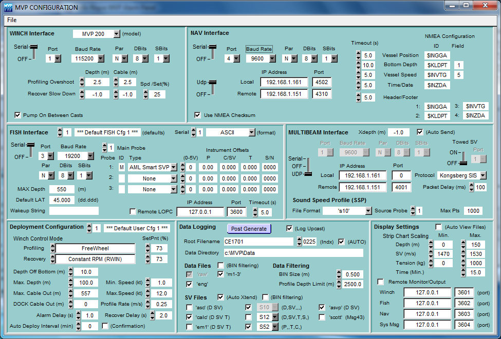
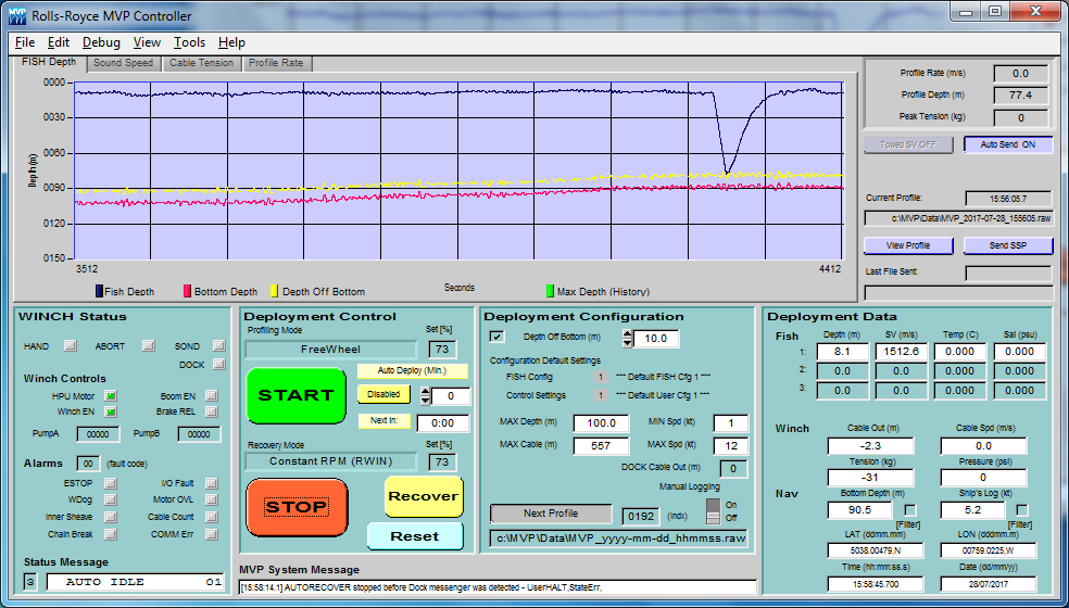
| Screen shot 1 |
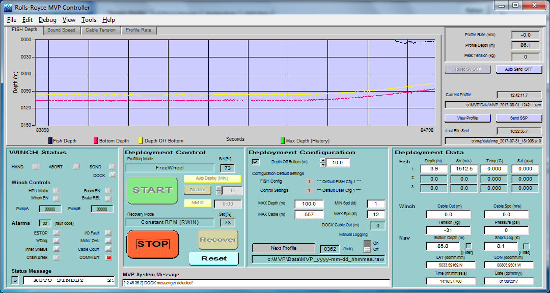 |
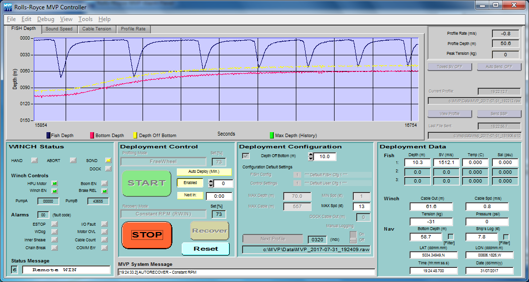
| Screen shot 2 |
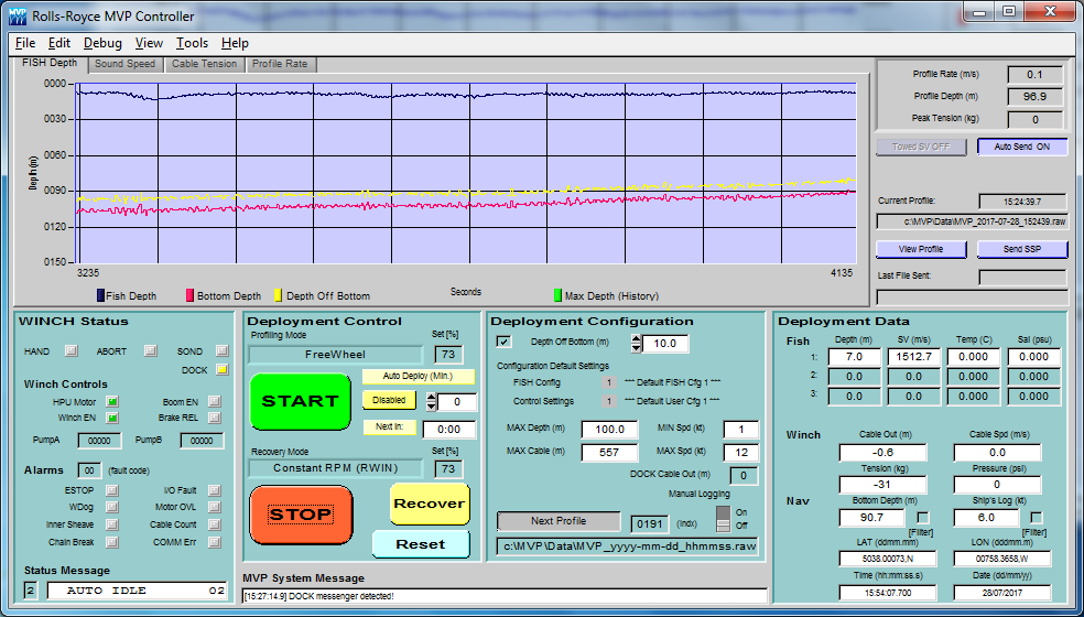 |
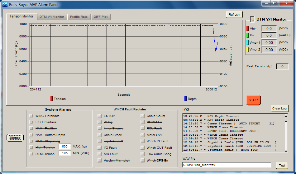
| Screen shot 3 |
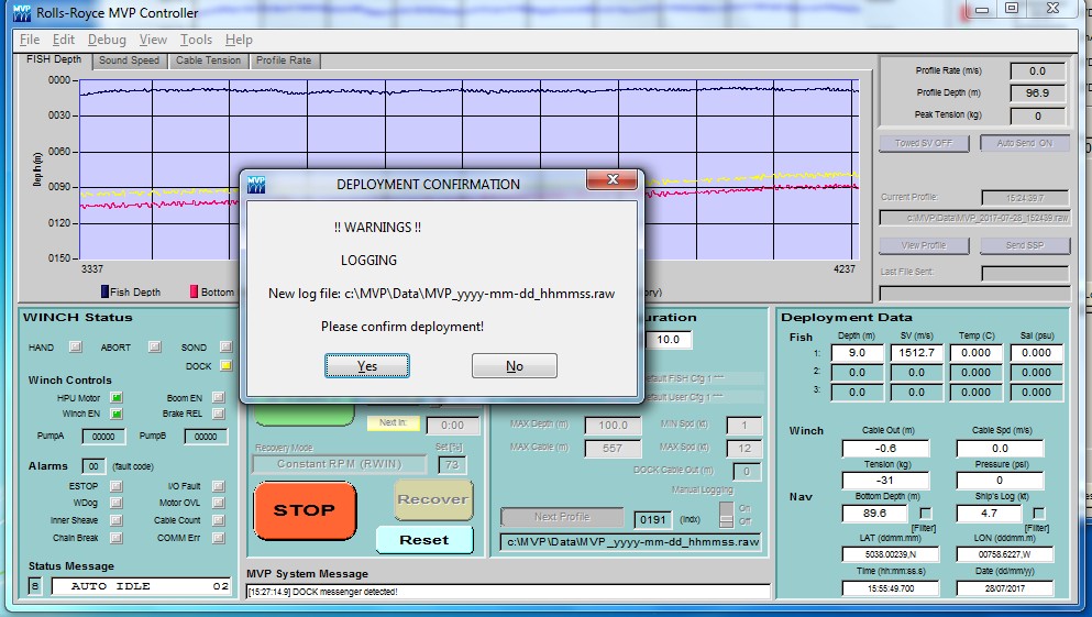 |
| Screen shot 4 |
 |
| Screen shot 5 |
 |
| Screen shot 6 |
| Screen shot 7 |
 |
| Screen shot 8 |
 |
| Screen shot 9 |
 |
| Screen shot 10 |
 |
| Screen shot 11 |
 |
| Screen shot 12 |