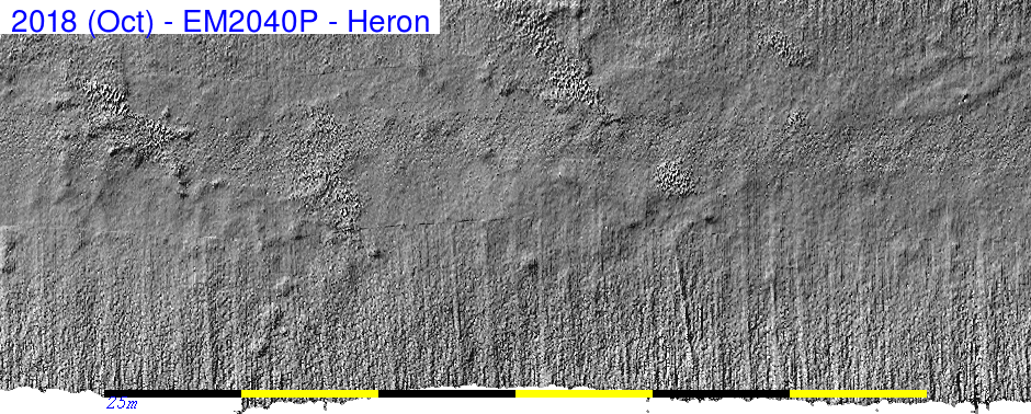
CSL Heron 2018 Operations
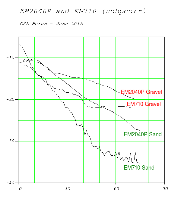
EM2040P Testing
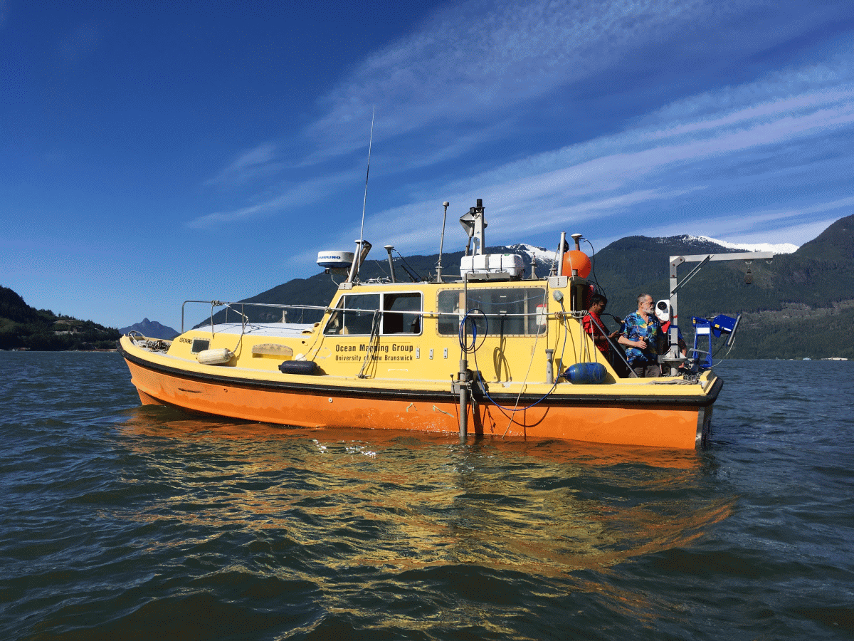
CSL Heron, Sidney, Race Rocks, Squamish, BC
June 15th to 29th, 2018
John E. Hughes Clarke
|
Ian Church
|
Anand Hiroji
|
Center for Coastal and Ocean
Mapping
University of New Hampshire
|
Ocean Mapping Group
University of New Brunswick
|
Dept. Marine Science
University of Southern Mississippi
|
|
|
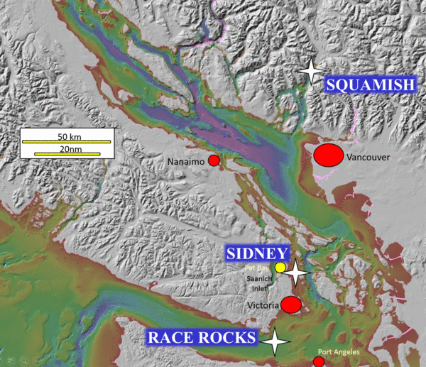
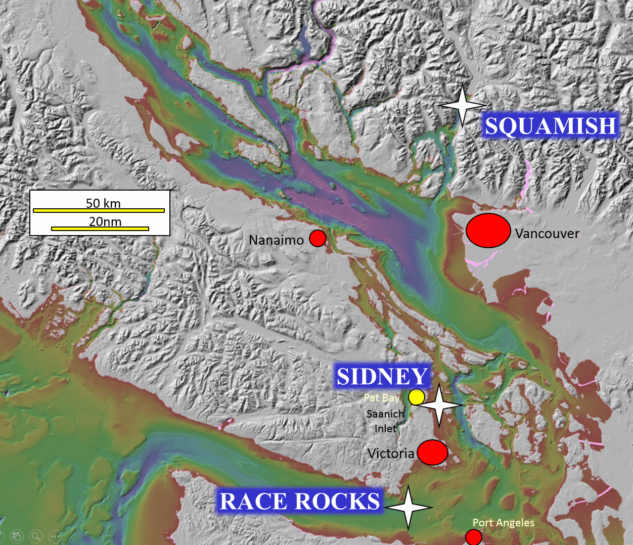
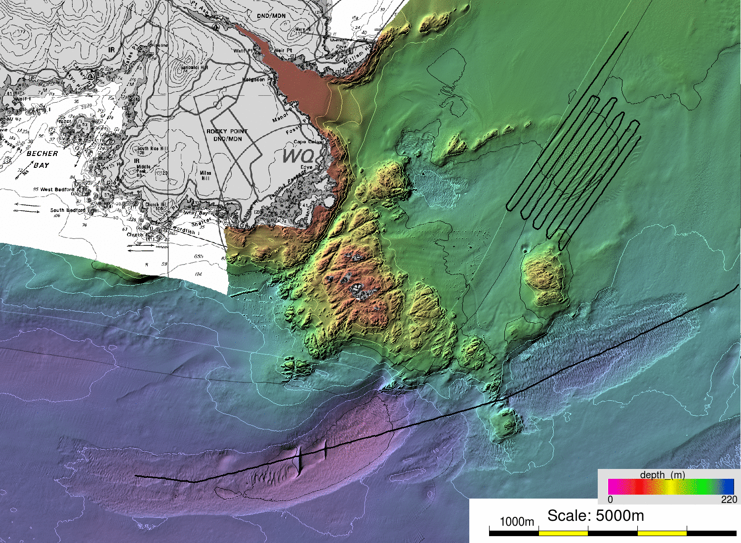
Main operational areas - SW British Columbia
|
Overview
and Experimental Intent
An EM2040P system was kindly loaned to a group of researchers from
UNH, UNB and USM for joint testing operations for a period of about
2 weeks in June 2018. The system was picked up from, and returned
to, the Mesotech office in Port Coquitlam. The system was first
installed in Squamish (not operating for this first period) and then
primarily used in the Sidney and Race Rocks areas. At the end the
system returned to Squamish and collected more data there.
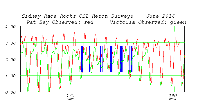
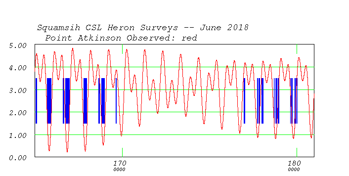
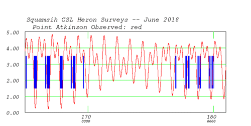
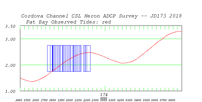
The Sidney-Race Rocks area was the prime test site. During the
operational period however, the tides were at their Neap conditions
as the Spring tides were required for the Squamish operations:

showing Heron operational windows (blue
boxes) during
the Sidney and Race Rocks experiments. |
showing Heron operational windows (blue
boxes) during
the Squamish experiments - NOTE** - EM2040P only
used in second window
|
In transit between the two, brief surveys were conducted off Sands
Head. But as there was no overnight stop (which routinely occurs in
April and October transits), the EM2040P was not deployed and thus
no information on the Steveston Channel Salt wedge was obtained.
This would be an excellent future experimental target.
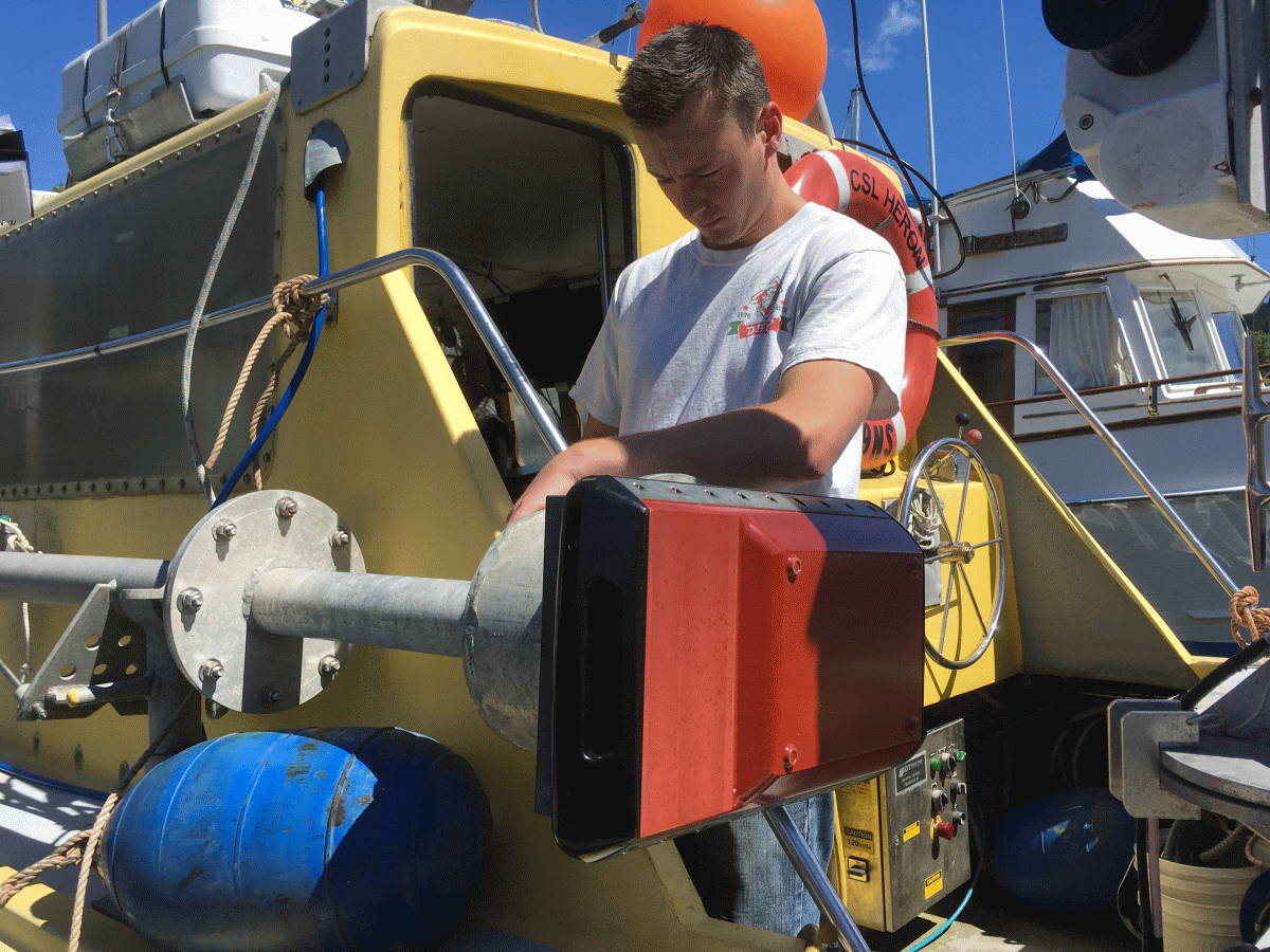
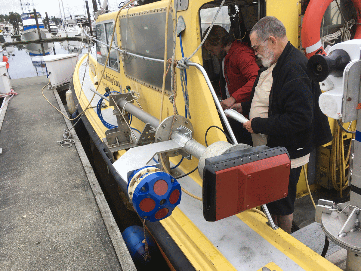
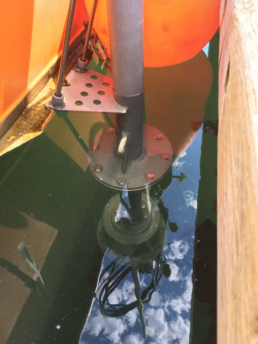
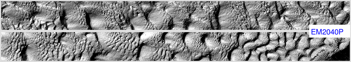
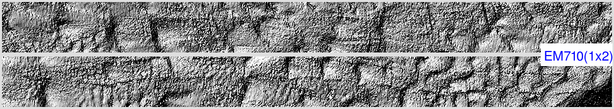
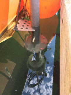
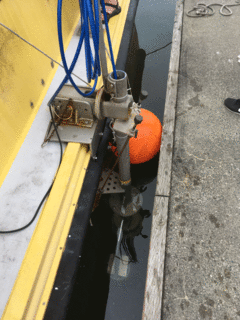
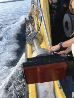
Installation
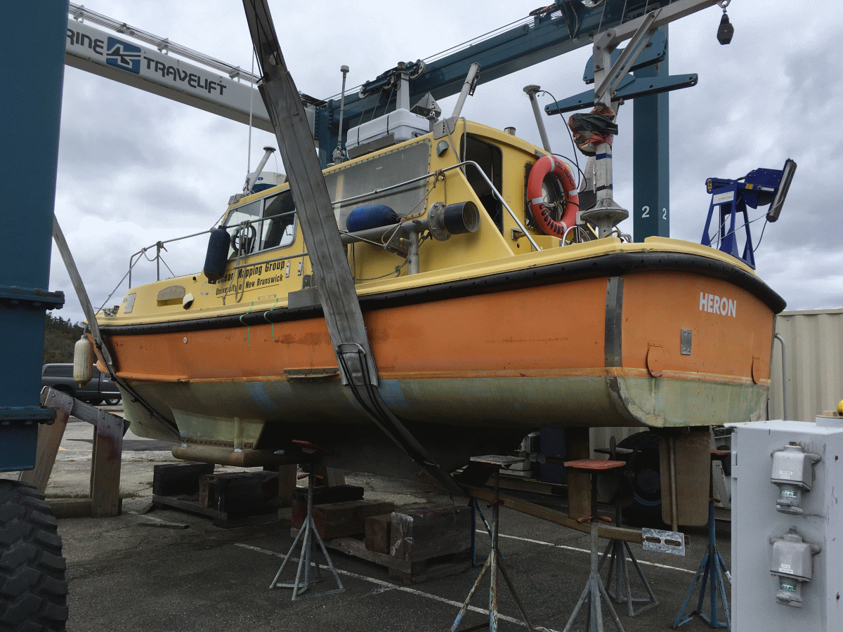
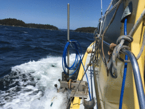
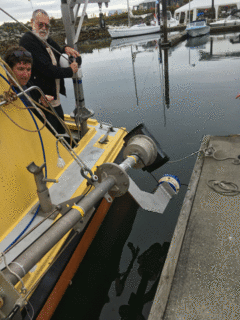
The 2040P was installed on a pole mount on the port side of CSL
Heron. The Heron is a 10m survey launch, owned by the Canadian
Hydrographic Service, on long term loan to the University of New
Brunswick. She is based at the Institute of Ocean Sciences in
Sidney BC. She has a permanently installed EM710 (1x2) on a gondola
on her port side:

showing the port side with the gondola and the pole
mount aft |
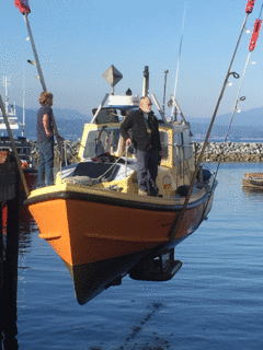
showing the gondola during launching |
The EM2040P was integrated with a POS/MV 320 v.5 utilizing CNav RTG
corrections. Sound speed profiles were obtained from an MVP-30 that
is capable of underway profiles to ~ 30m and maximum stationary
profiles to 125m. Deeper profiles were either obtained from a
manually lowered AML-SVP-16 or from archived DFO data (MEDS).
The Heron was operated by Gordon Allison, and additional logistical
support and mount construction was provided by Mike Boyd of Polar
Diving.

|

|
|

|
pole mount on port side
|
install on base of pole
|
underway
|
install with ADCP ahead
|
|
|
|
|
|
|
as usually deployed (no ADCP)
|
offsets.
|
optionally with ADCP
|
pole - recovered
|
deploying with ADCP
|
|
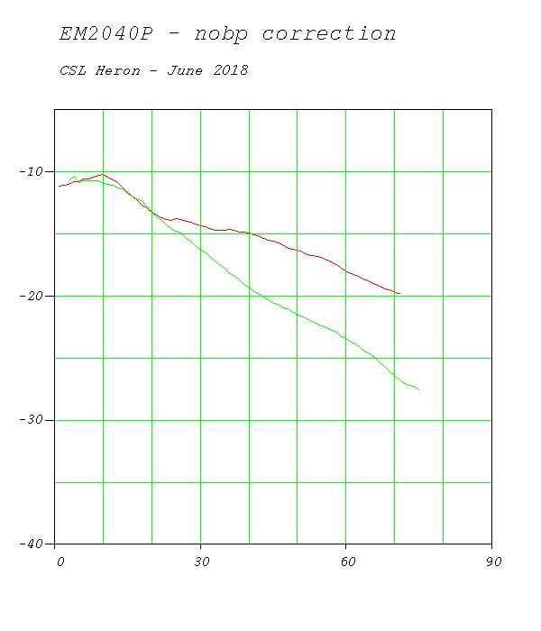
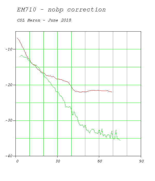
Issues Encountered
The system generally performed extremely well. Many of the teething
problems were related to our lack of familiarity with the new SIS-5
software.
The SIS-5 software - launched using the SIS controller, was set up
on a DELL Precision M3800 laptop running Windows 7 (JHC's box). Due
to lack of sufficient screen acreage, two separate external monitors
were connected so that the tear-off SIS-5 windows could be set up
and easily viewed (see photo below to left).
The most notable changes for us was the ability to use UDP network
telegrams for the orientation and the positioning.
Synchronization was attempted by using the two trigger lines into
both the EM710 and EM2040P. Each can provide a RTF and FIR
trigger. In general the EM710 was used as the master as it
would achieve a greater angular sector in deeper waters and its ping
rate was slightly lower due to having longer pulses in shallower
water.
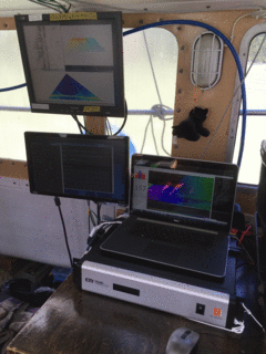
the 3-screen setup for the SIS-5 EM2040 controller
|

the distortion of the sidescan image trace in the
real-time display.
|
A few issues were, however, noted with the SIS-5 set up.
- Frequent disruption/freezing to the real-time displays and
logging - this, however, was probably related to our network and
disk storage configuration.
- Clear distortion of the real-time scrolling sidescan display
- this looks like the beam location to trace location index is
off?. Subsequent processing of the image telegram data showed
that these traces were fine.
- The synchronization was not very satisfactory - it clearly
works, but the multiple from the EM710 shows up in the following
EM2040P logging so it was rarely used. See more discussion
below.
The performance of the 2040, in bathymetry, backscatter and water
column is addressed in the report below. The most immediately
noticeable issue, perhaps, is the fact that the inter sector gaps,
when yawing continue to be so prevalent.
KMALL format
As part of these trials it was necessary for the OMG swathed
software to start supporting the new kmall format. While it had been
announced for a few years, 2018 marked the first year that systems
were actually being delivered with the new format. At this time
(fall 2018) we believe that only the 2040P is standardly delivered
with that. The 2040P that is installed on the UNH ASV actually has
the old SIS-4 using the old .all formats for backward compatibility.
During the field operations, only the support for extraction of the
bathymetric data was available. In the autumn, updates to swathed
were implemented so that the image trace information and the water
column telegram could also be assessed.
Work still to be done includes:
- properly understanding the method of removal of the KM TVG
function.
- properly parsing the parameter telegram.
- incorporating all the extra available qualifiers (which
swath, which physical beam etc..)
Nevertheless, in the field, comparisons of the bathymetric imaging
quality (compared to the co-mounted EM710 and archived EM2040S/D and
C datasets) could be done and this was used to decide on the
progression of events. This report includes those initial results as
well as the backscatter and water column results apparent later.
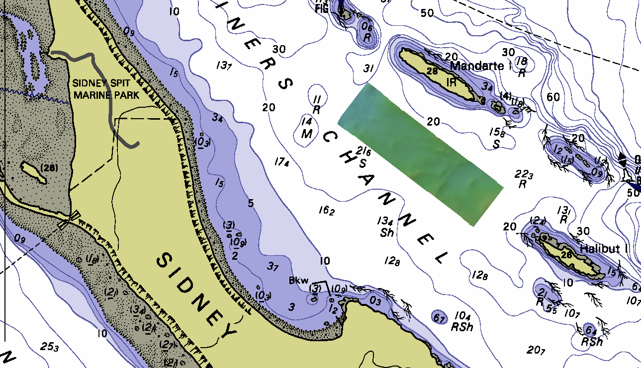
Sidney
Operations
Operational Area
The waters from Saanich Inlet to the Gulf Islands around Sidney BC
have a wide variety of oceanographic conditions and exhibit a wide
range of seabed features useful for testing sonars. These have
previously been extensively used since 2011 for all the NAVOCEANO
HSL trials (EM2040S and EM2040D). Most of the subsequent Heron
operational testing in the area has reoccupied these common
reference areas to compare the output of various other sonars. To
date, we have utilized M3, EM710 (1x2) and EM2040C on all these
sites. Additionally there is older archived EM3000 and EM3002 from
the CHS covering these regions.
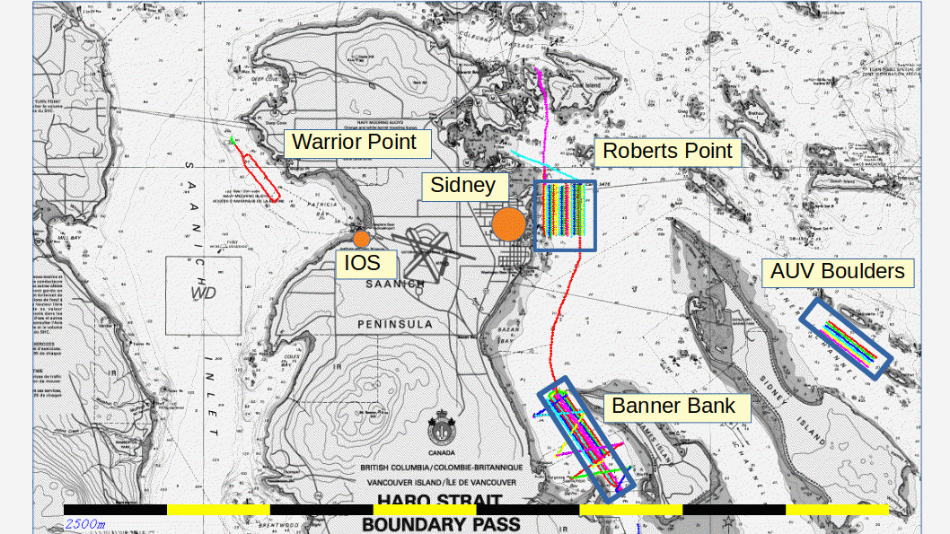
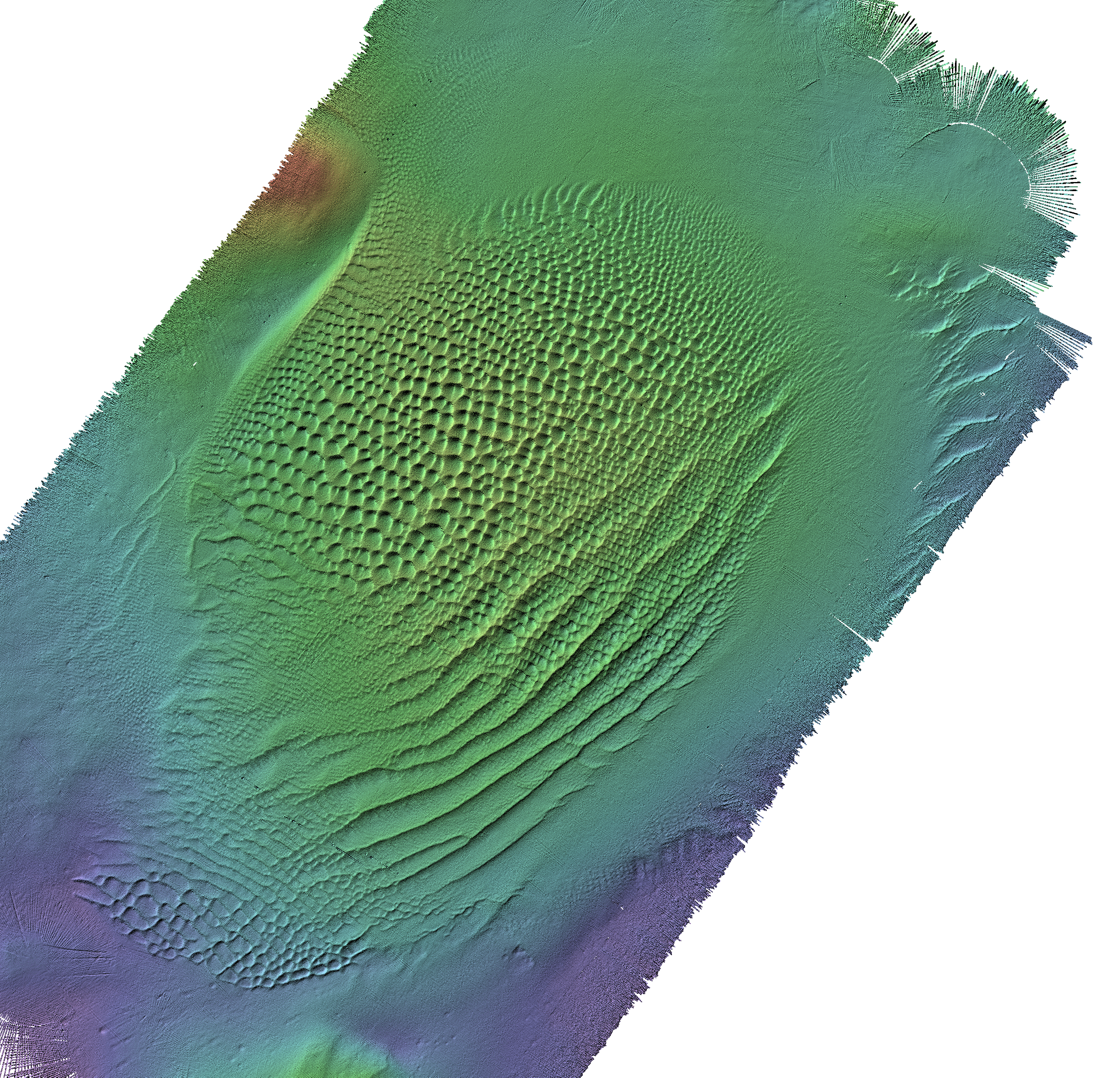
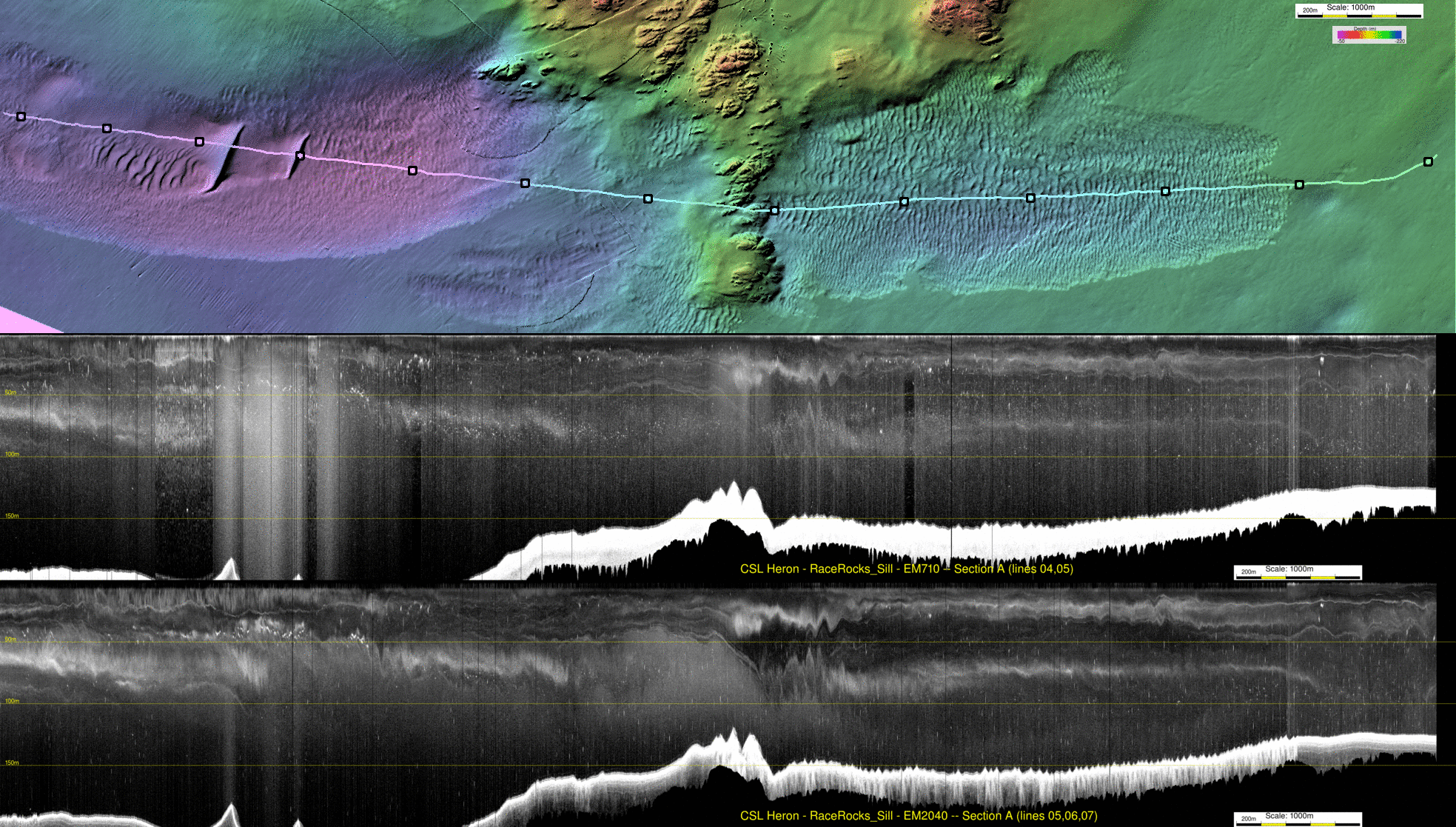
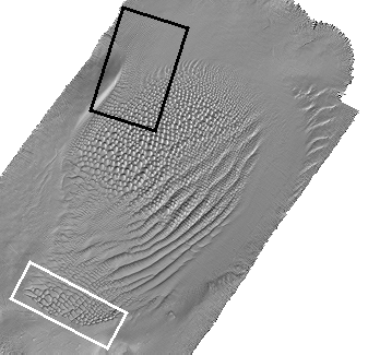
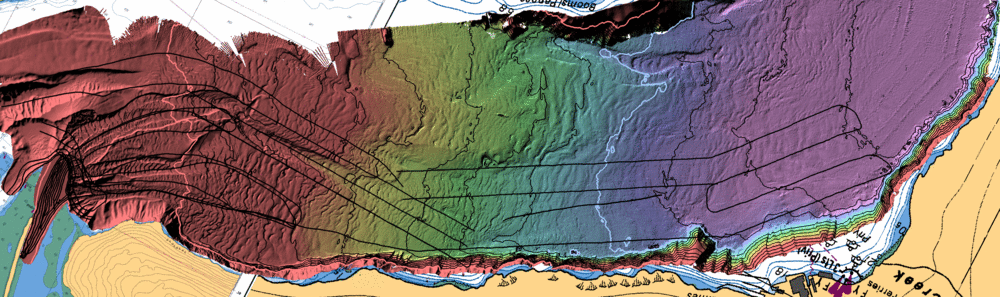
regional map showing the location of the main test areas.
IOS: Institute of Ocean Sciences (CHS West Coast office)
This initial testing period we focused on three locations (see map
above):
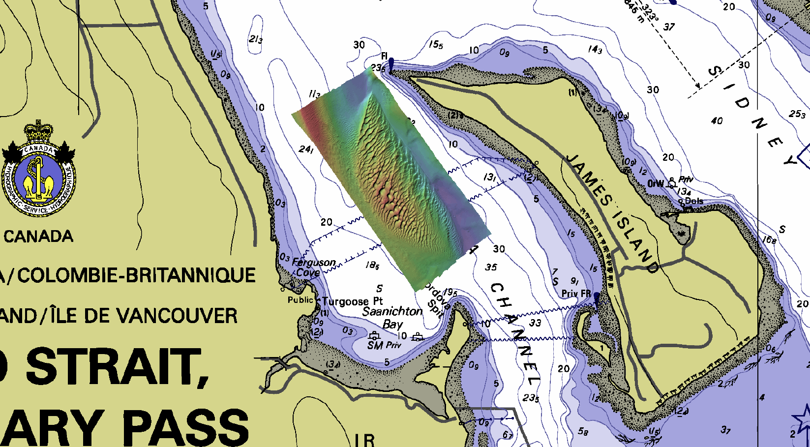
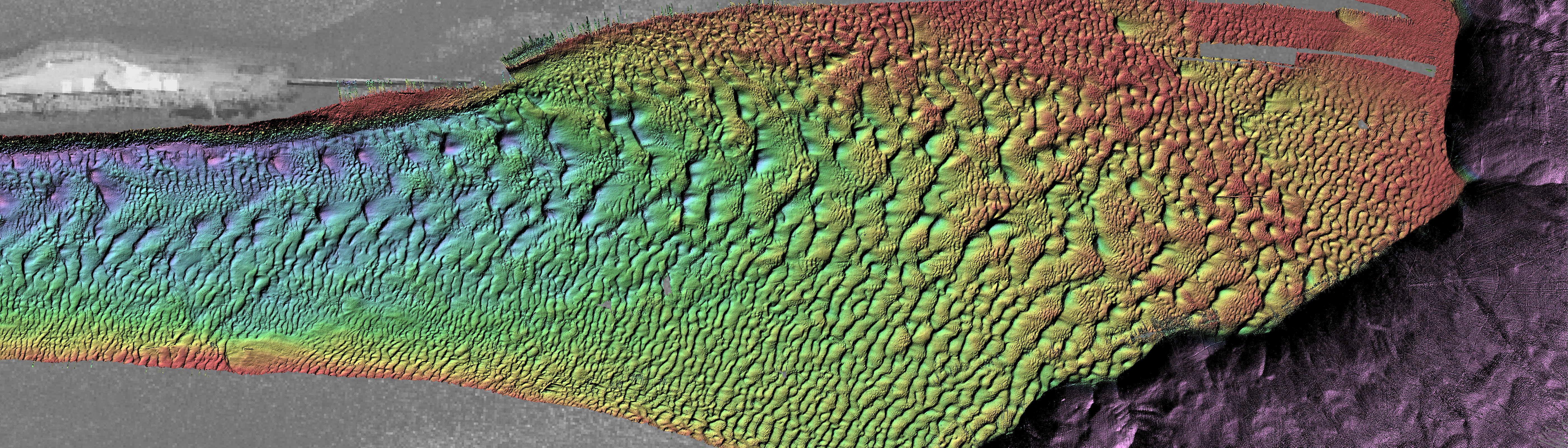
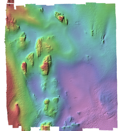
Cordova Channel
sand wave field ("banner bank")
The Cordova channel is an area in which a well developed "banner
bank" results from both:
- an ebb-tide eddy formed from south-flowing water in the lee of
the north end of James Island
- a flood-tide eddy formed from north-flowing water in the lee
of Cordova Spit.
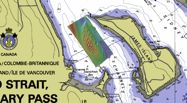
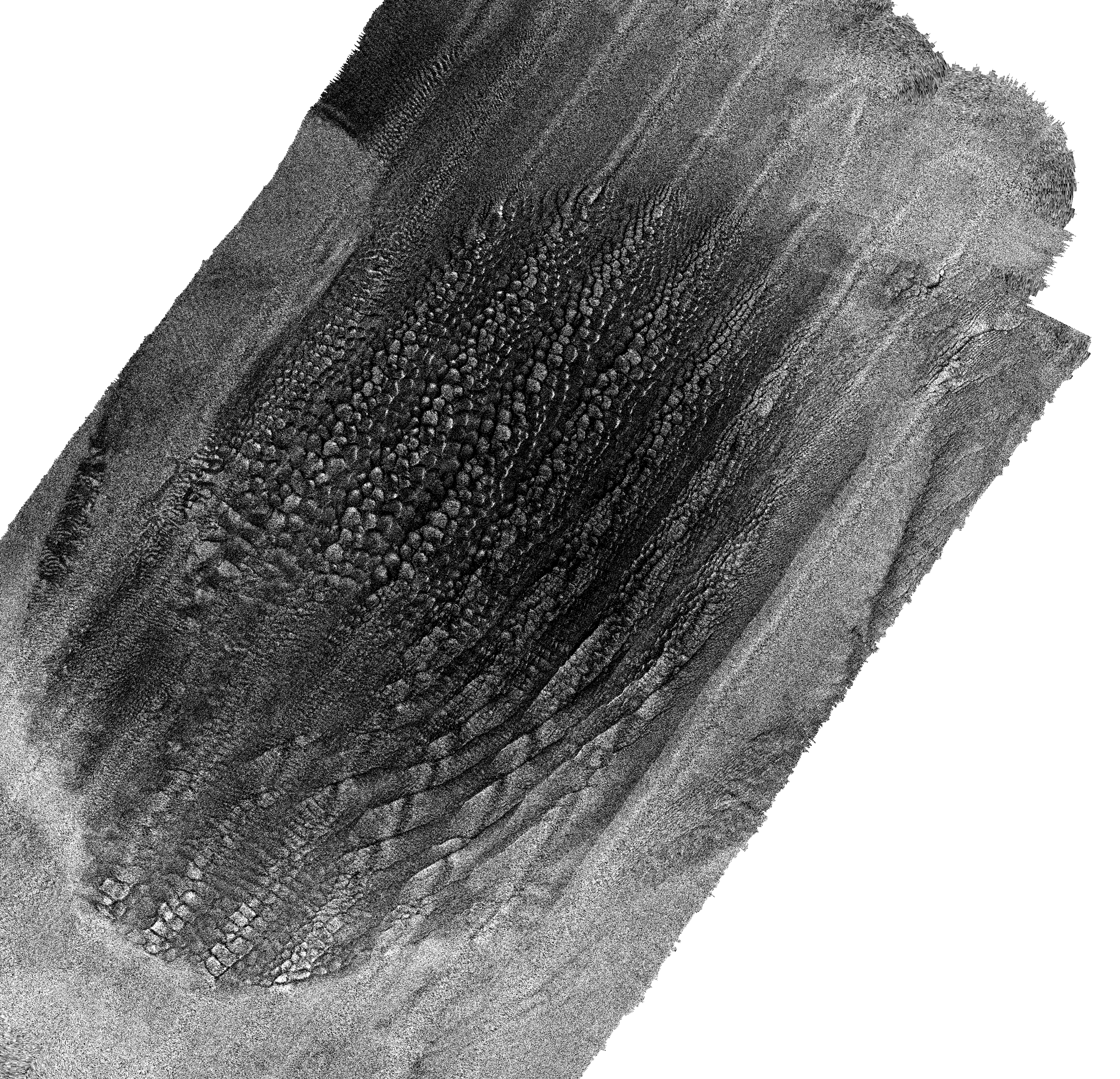
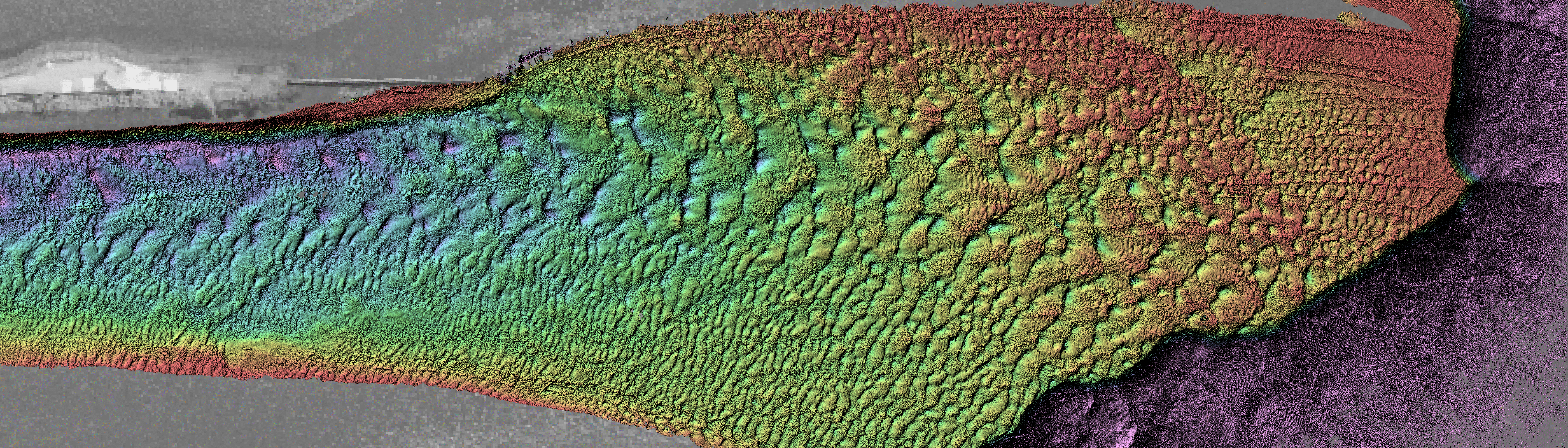
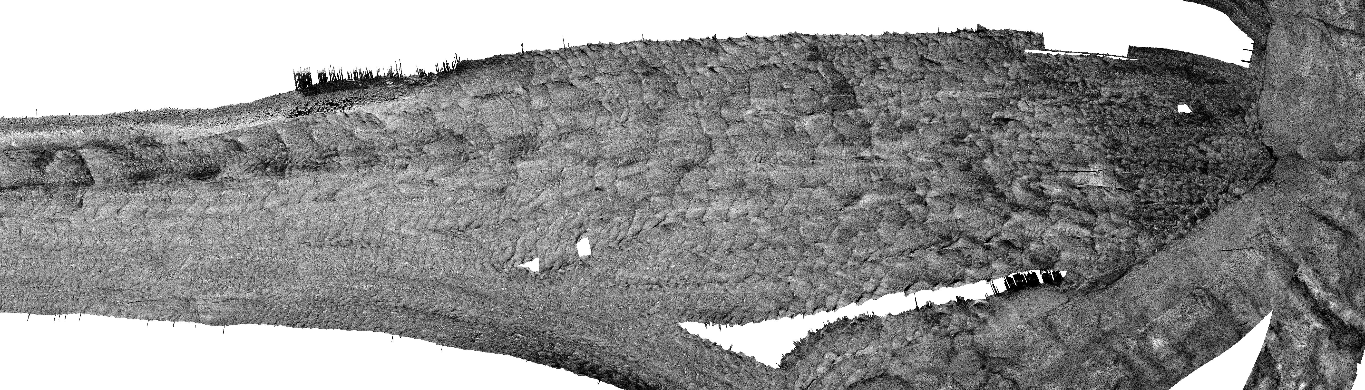
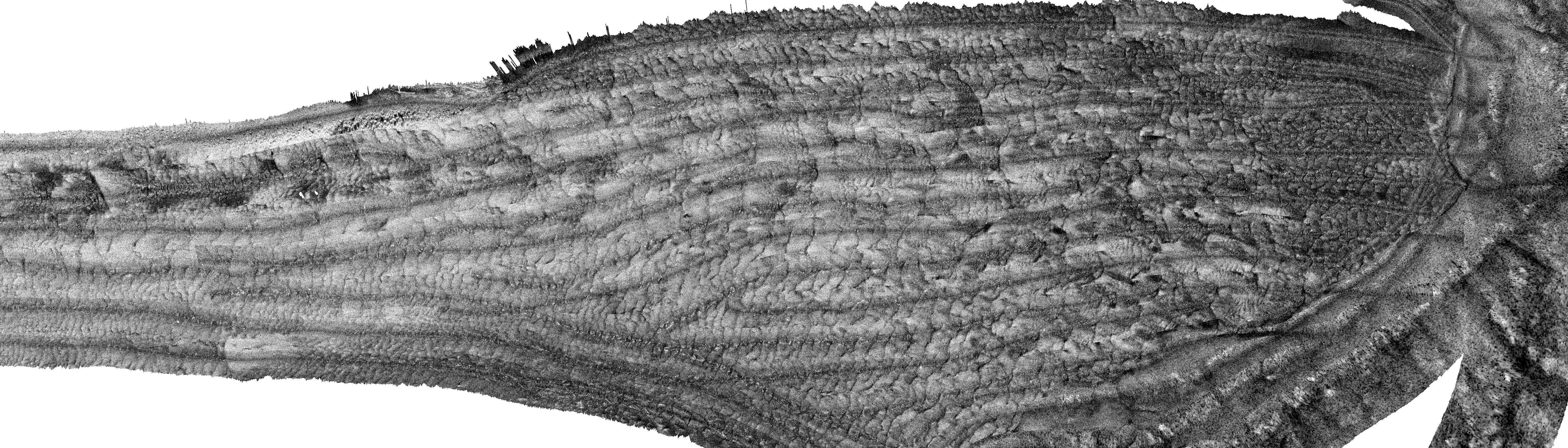
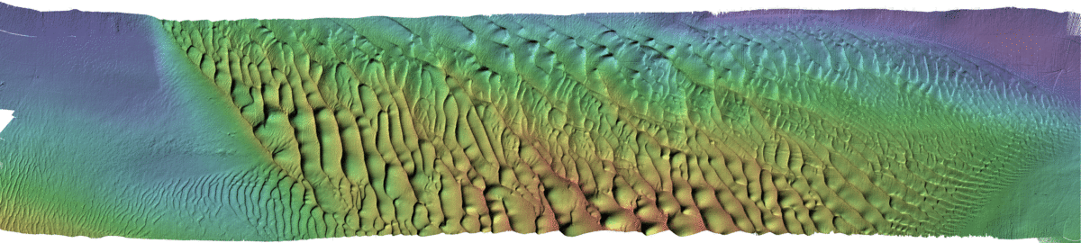
showing the banner bank situated in the centre of Cordova Channel
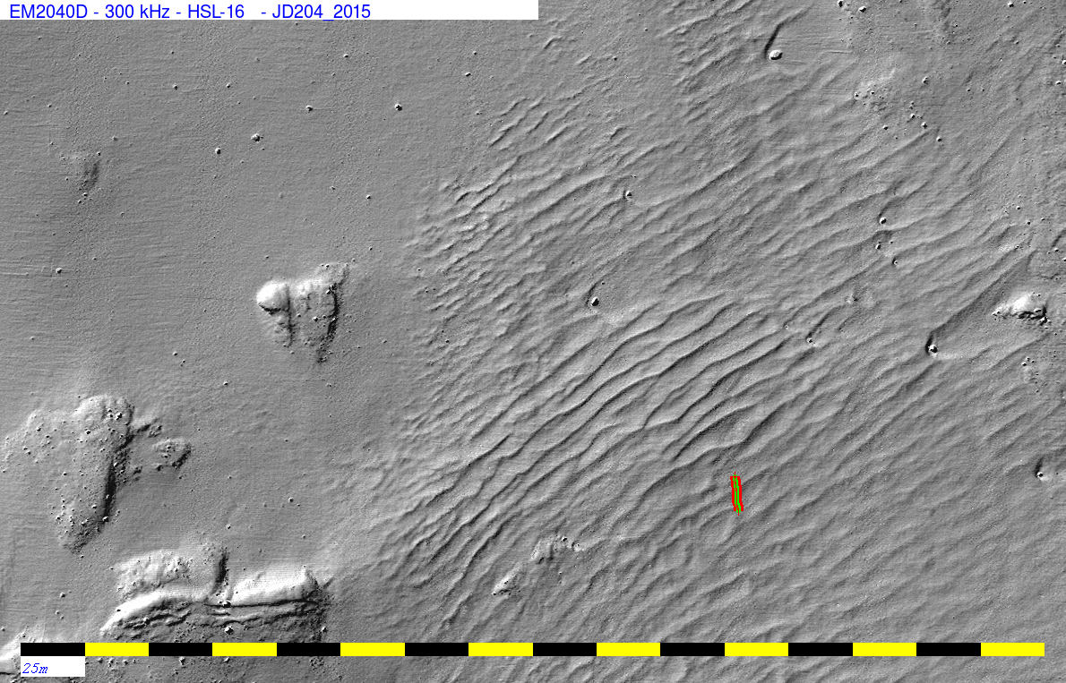
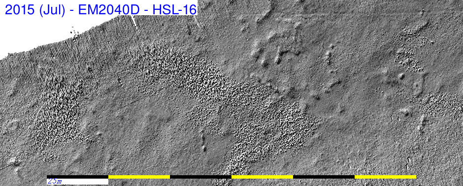
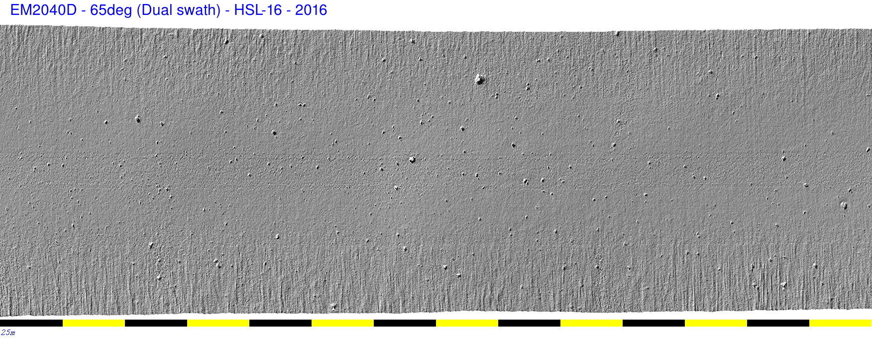
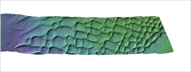
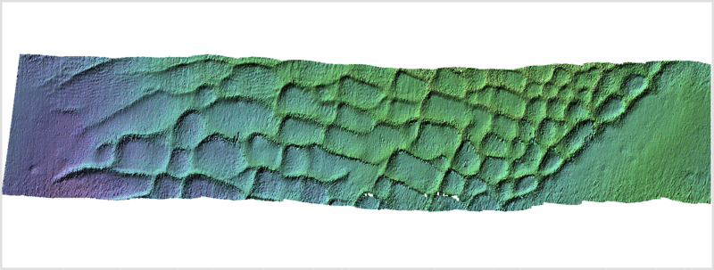
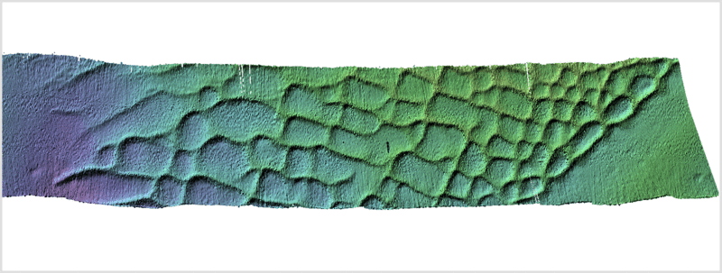
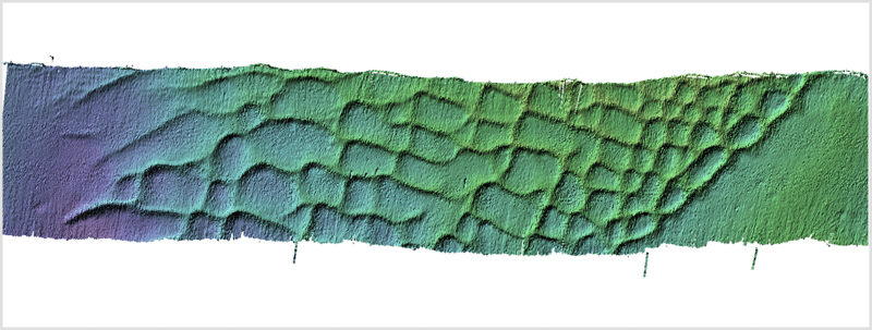
This area is well known for its active bedform migration. Notably,
from the HSL-!6 in 2016, a time series of bathymetric surfaces
demonstrated the rapid migration pattern over several tidal cycles.
Additionally in 2013 and 2014, it was demonstrated that the bedform
crests actually locally reverse from flood to ebb tide. From testing
in 2014 to 2016, it is clear that, on the full spring flood and ebb
tides, there is significant sediment resuspension which is clearly
picked up by the EM2040 water column imagery. Unfortunately,
however, for logistical reasons these 2018 surveys were done in the
neap tide window.
Additionally we have done extensive work here with bottom samples
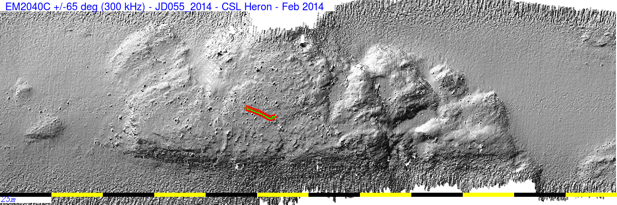
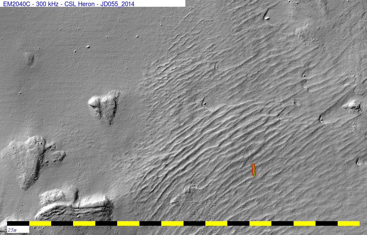
and photos. Most notably the second attempt at multi-spectral
imaging was performed here in February 2014 using the CSL Heron with
EM710 and a loaned EM2040C. Those results were reported in the
2015
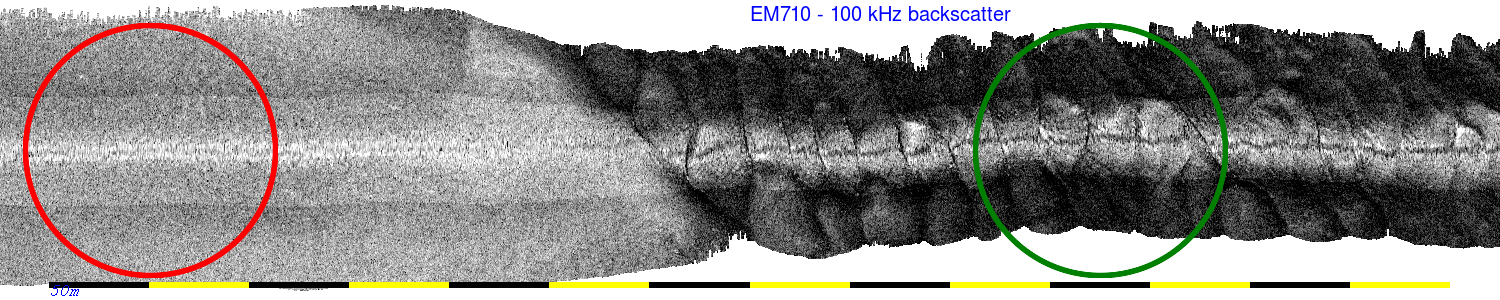
USHC conference paper. The pertinent figure is
reproduced here:
This year we just occupied a subset of the centre of the banner bank
field to attempt the following:
- Assess the performance of the EM2040P w.r.t. other systems
(2040C and 2040D).
- Try to repeat the multi-spectral testing here - which requires
attempts to reduce the EM2040P residual sector beam pattern.
- to see if we could catch bedform changes from tide to tide
- to see if we could catch the suspended sediment phenomena
during peak flood or ebb tide (not successful).
- Undertake a short ADCP survey during the falling tide.
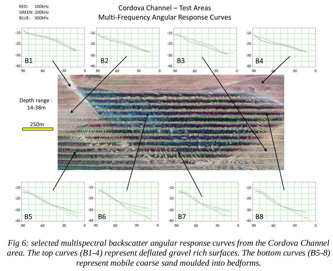
Multi-spectral
Coverage
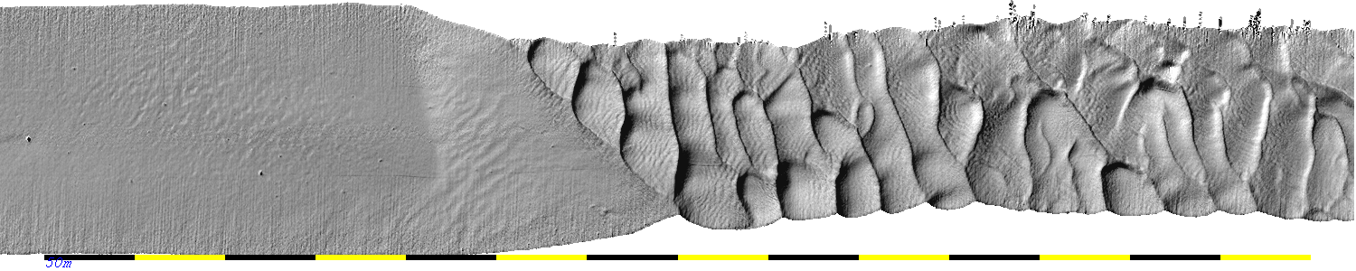
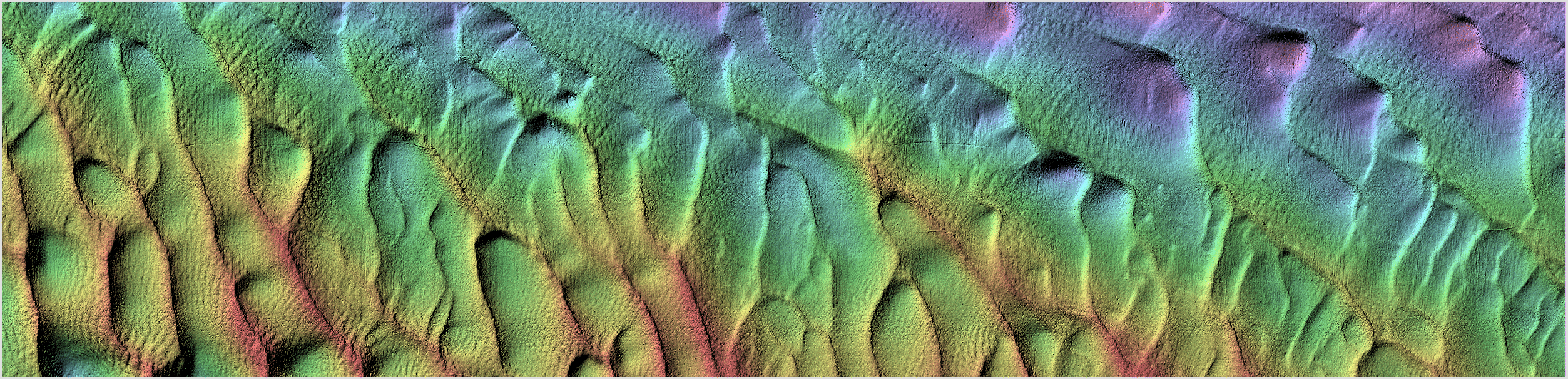
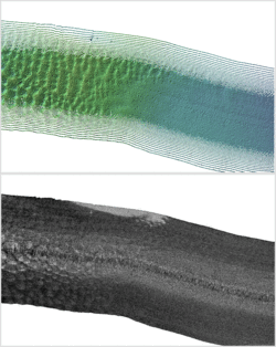
The following images show the JD173 survey:
bathymetry from the EM2040P

backscatter from the EM2040P - greyscale -10 to
-30 dB
note this has had a rolling, adaptive angular response removal
process so that you don't see the grazing angle signature.

backscatter from the EM710 - greyscale -15 to -35 dB
Combined Red-Blue product with 710 (red) 2040-300kHz (blue)
EM2040P Pulse lengths setting: all using the 0.101ms pulse
EM710 using the 0.16 ms pulse (Very Shallow)

|
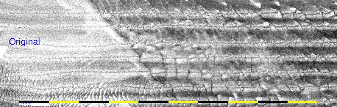
The plots above have had the shape of the angular response
heavily suppressed. On a 500 ping basis, the average shape
(variation with grazing angle) has been estimated and
removed. In reality, however, that angular response is
extremely valuable.
 animation showing original data before
and after adaptive ARC estimator
animation showing original data before
and after adaptive ARC estimator
As with the data collected in the original 2014
multi-spectral surveys, there is significant grazing angle
variability in the backscatter strength and that variability
is very sediment type dependent AND frequency dependent.
While this confounds the attempt to make a "pretty" mosaic,
it actually provided significantly more degrees of freedom
in attempting remote seafloor classification.
|
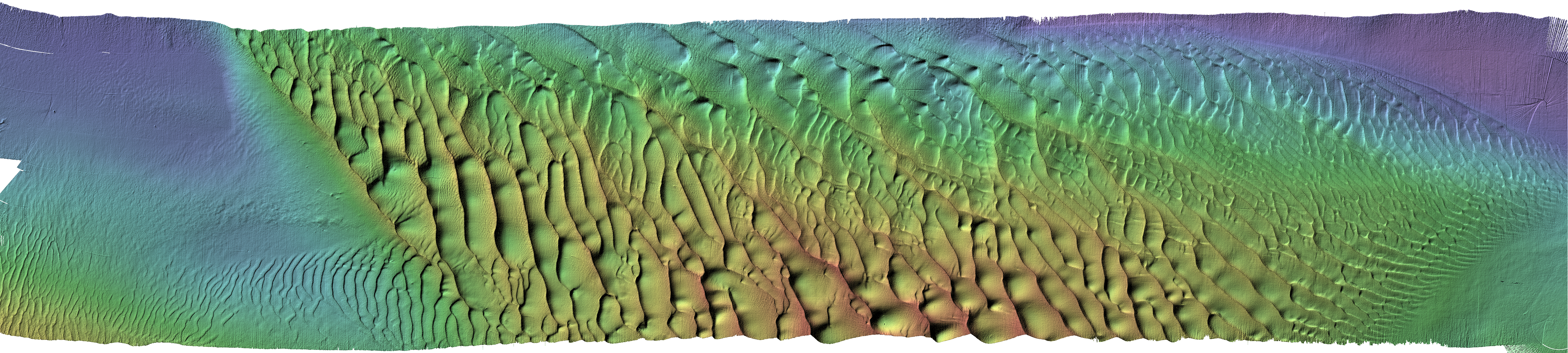
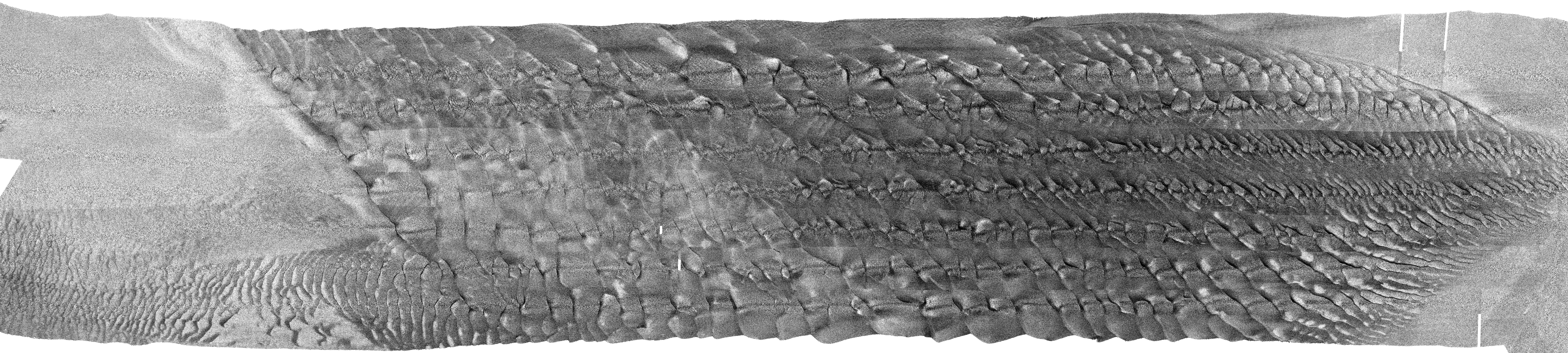
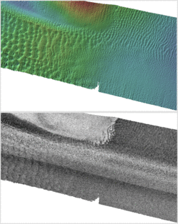
Changes over the 2
day period
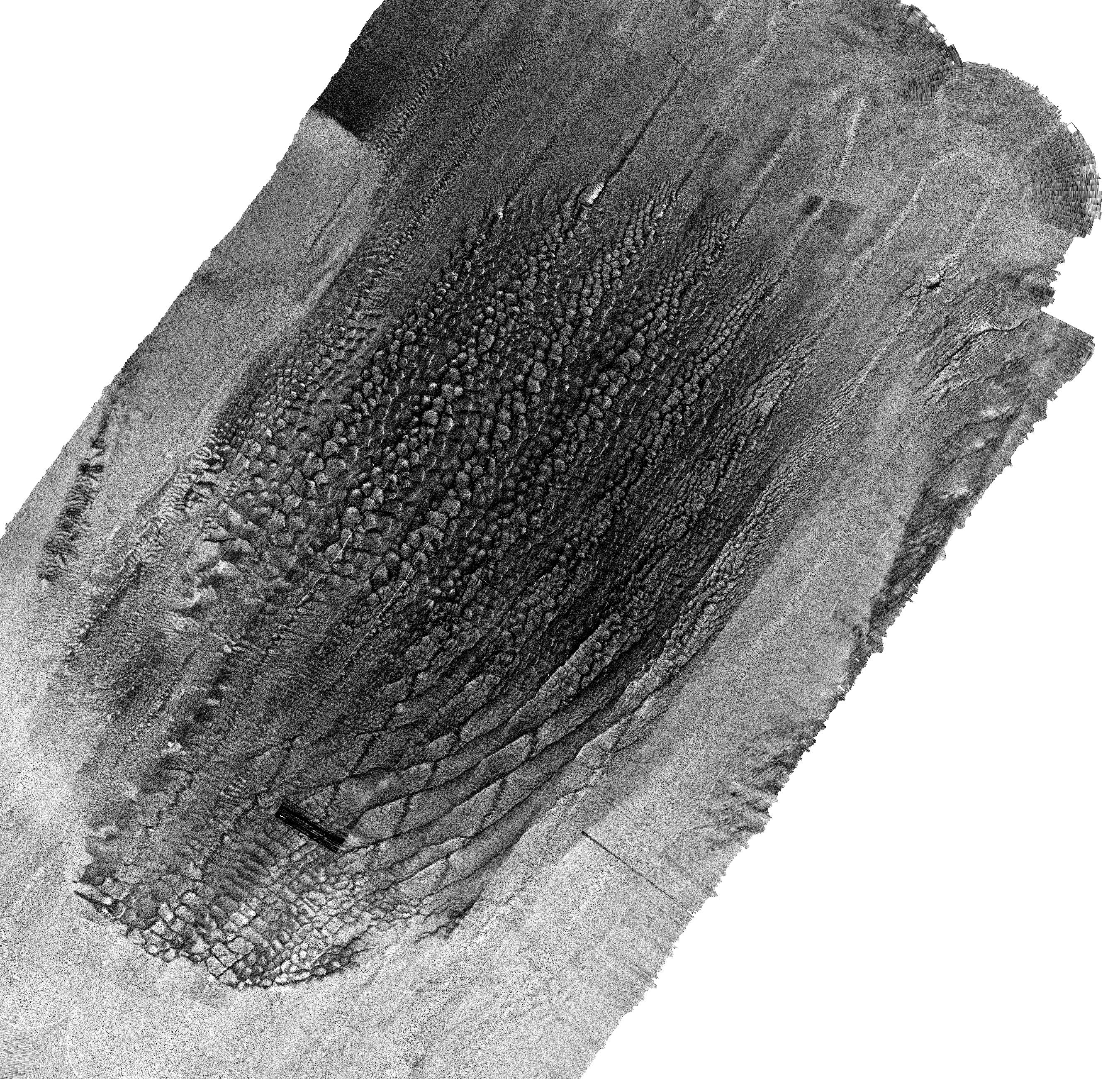
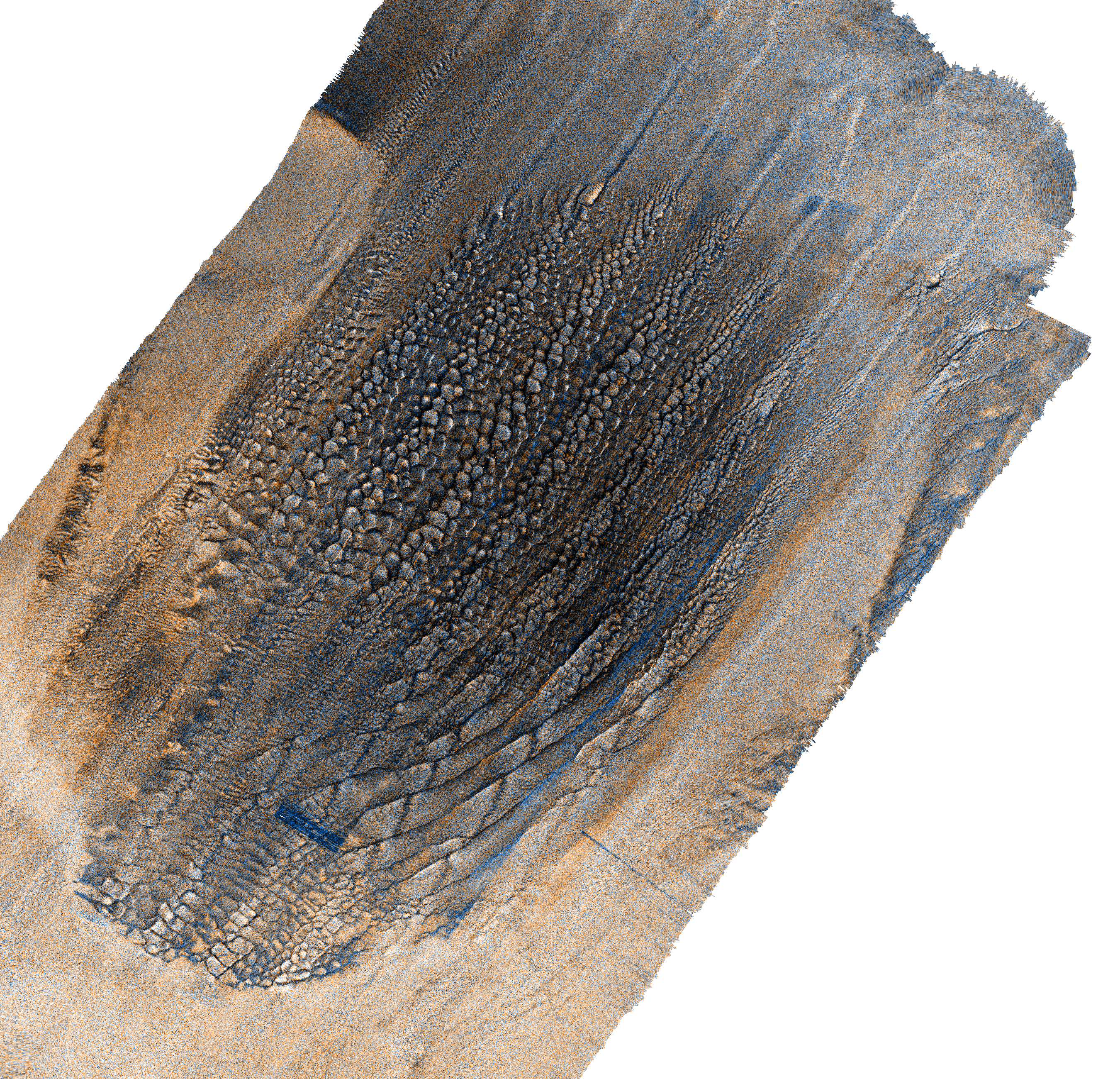
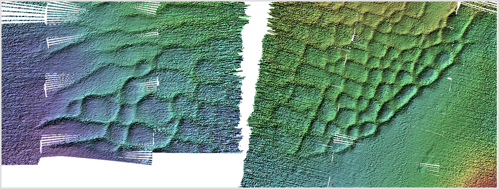
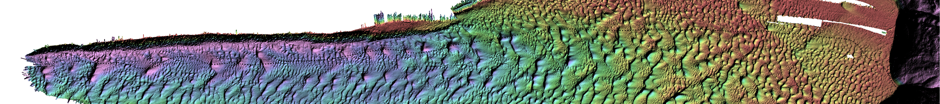
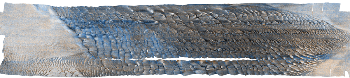
We performed two survey of the bank, 2 days apart (JD171 and JD173).
In that time, even though neap tides, there was notable movement of
the dune crests and this was faithfully captured by the EM2040P:
 animation of same area - 2 day apart - notice
that the larger crest have migrated one way,
animation of same area - 2 day apart - notice
that the larger crest have migrated one way,
whereas the smaller population on the crest have migrated the
other way (and been truncated by the larger crest).
The results above, presented at a 50cm grid (on click, in the
visible page here it is 1m), confirm the quality of the C-Nav
positioning and the system integration (patch test etc..). However,
it really doesn't address the resolution limit of the 2040P. For
that we have to take the same data and compare with other sonars.
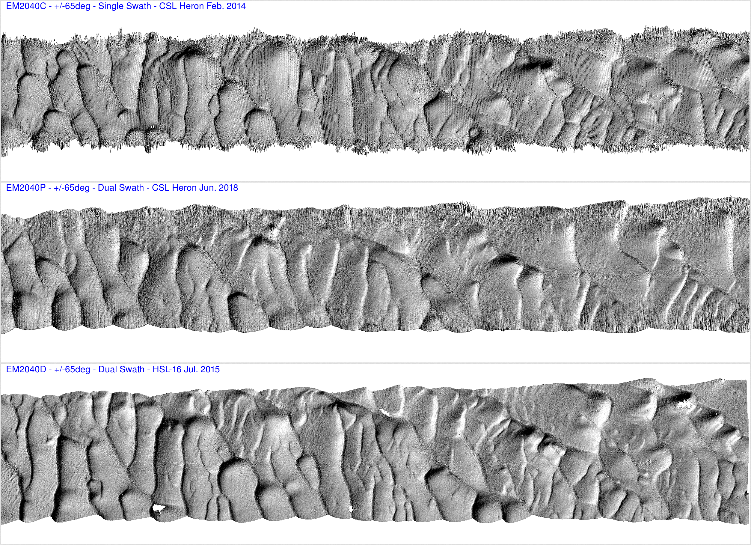
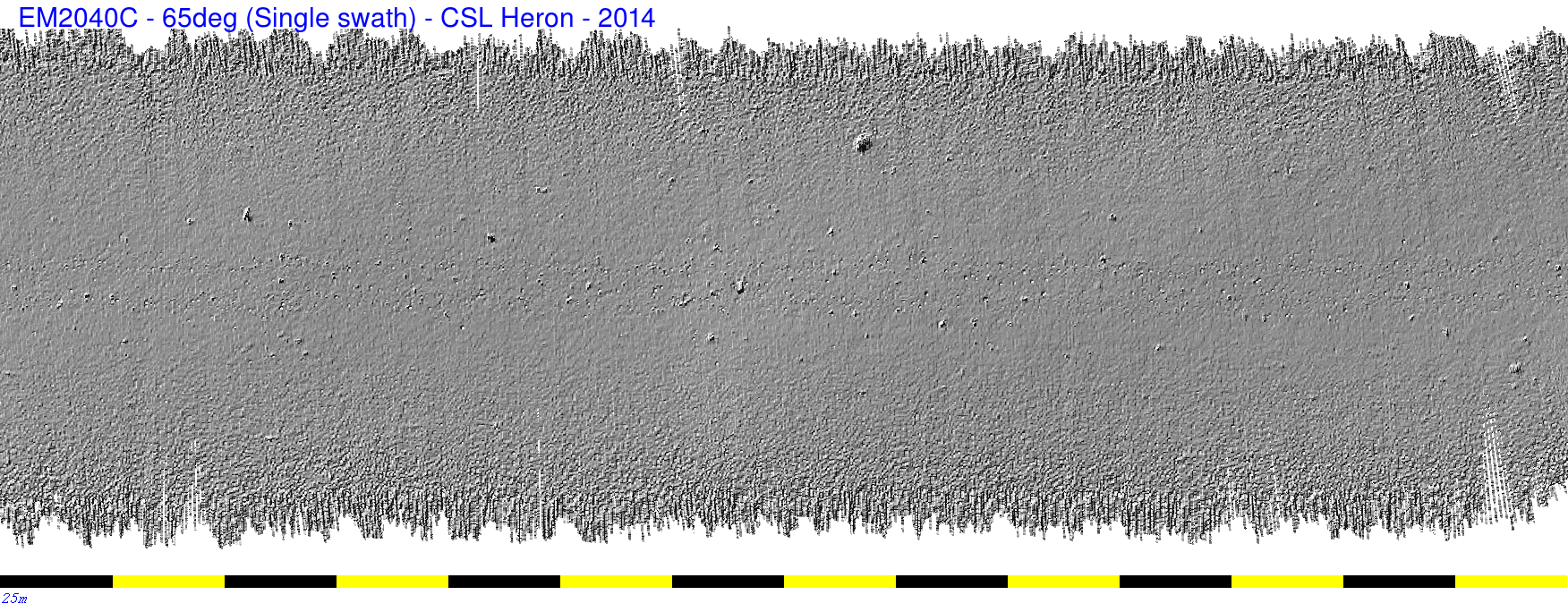
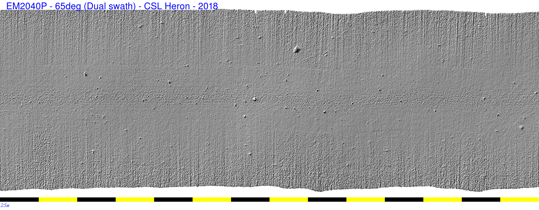
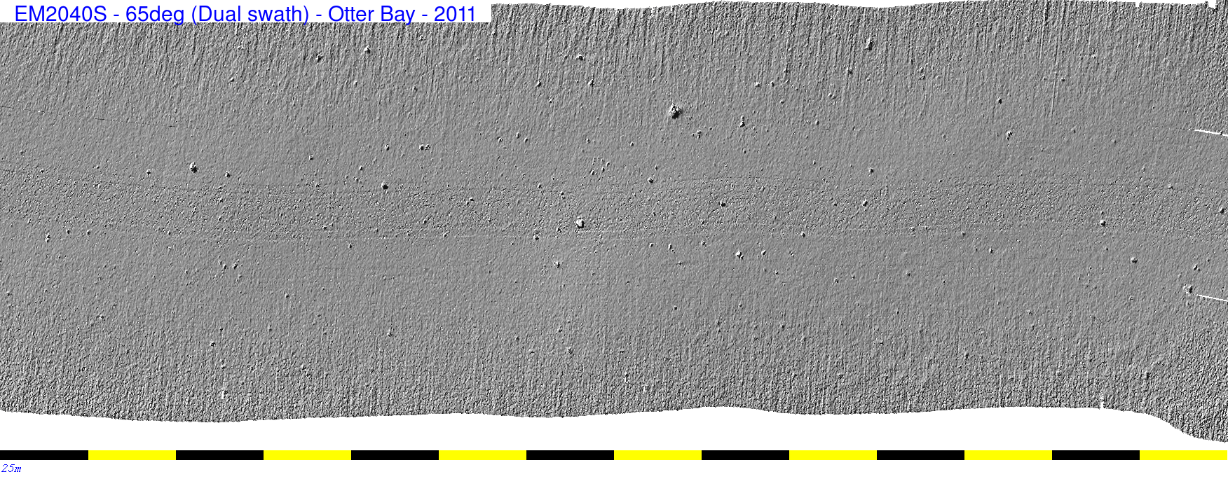
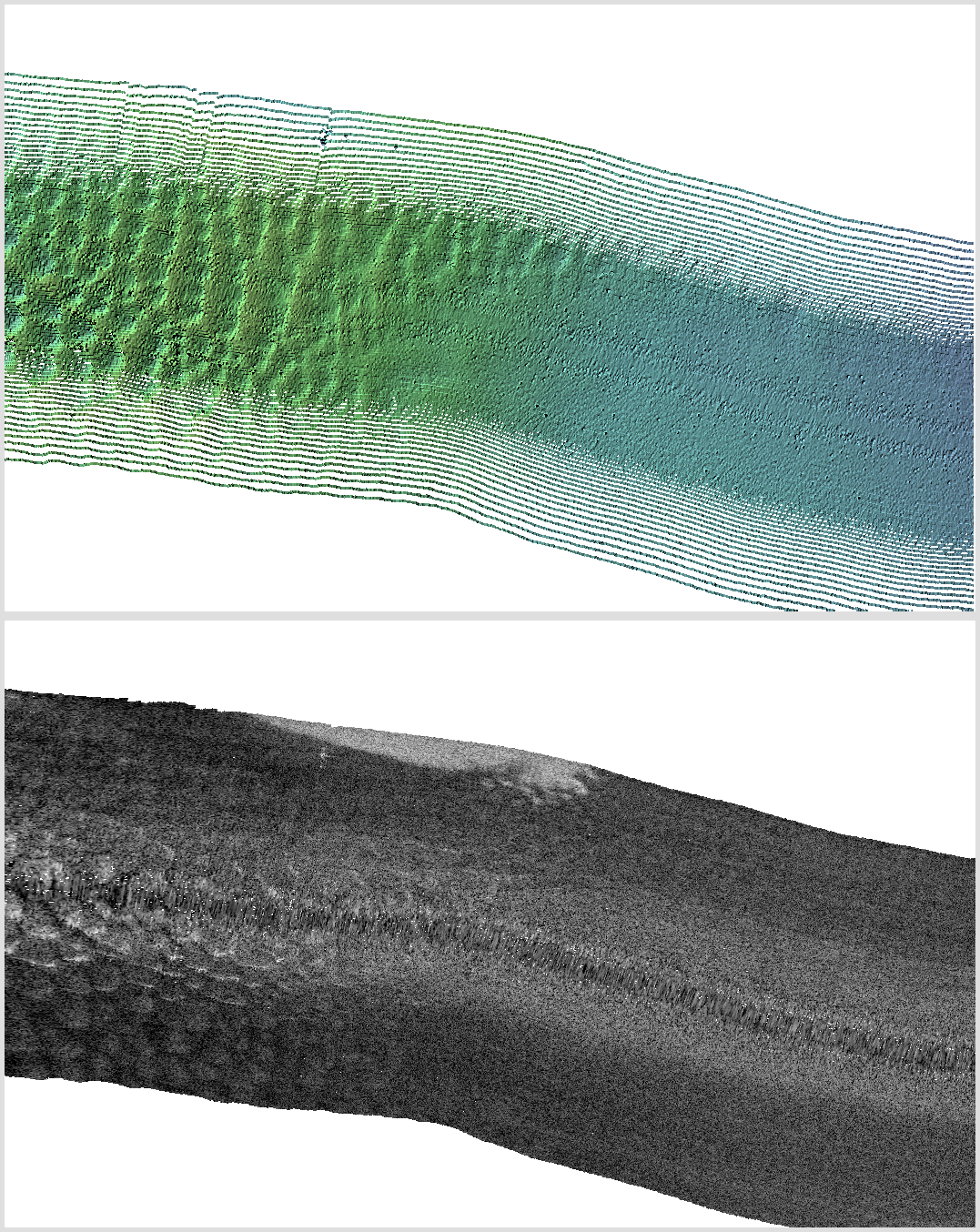
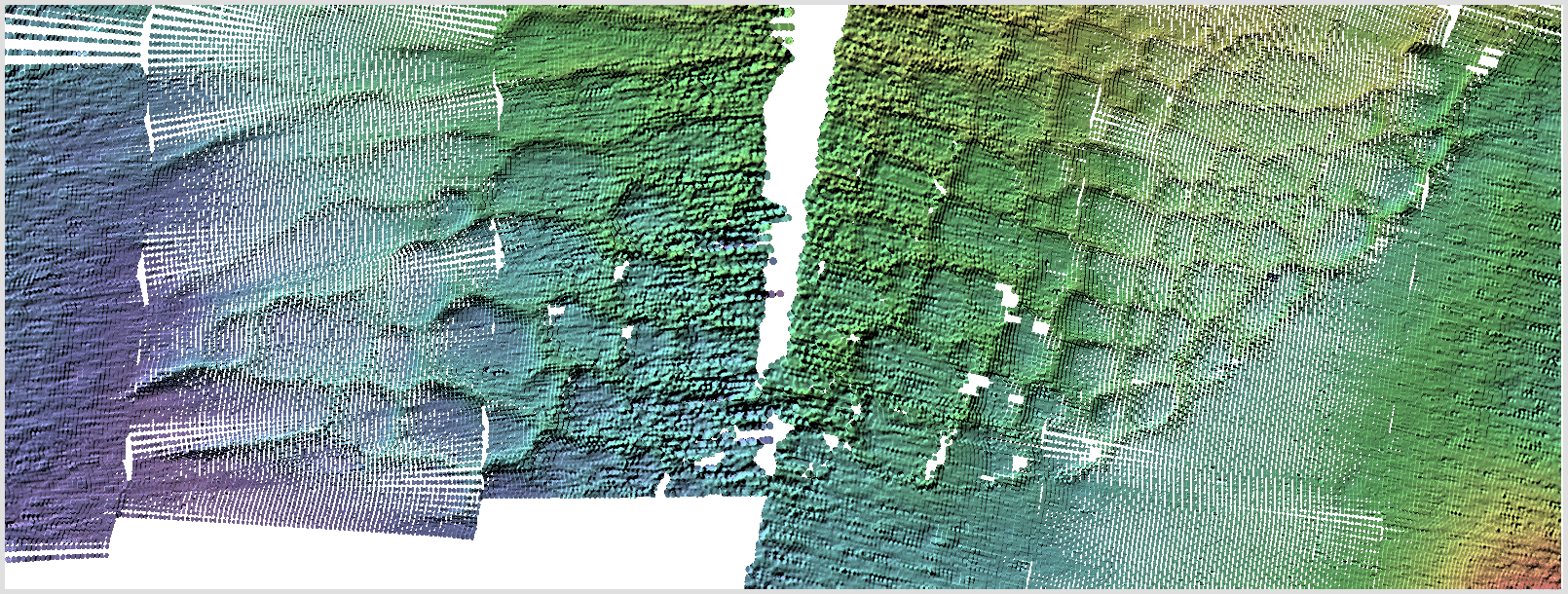
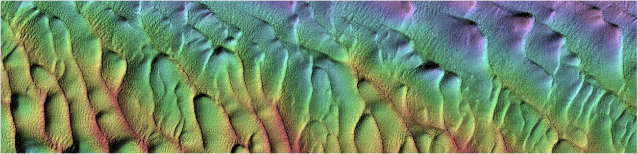
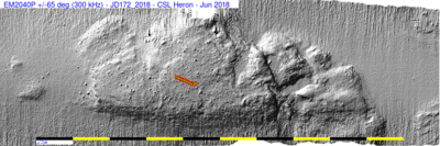
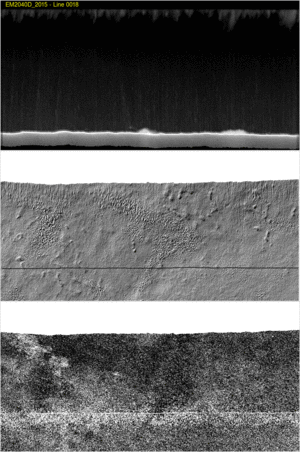
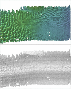
Comparison
of resolution with 2040C and 2040D
Again we will compare the same line with the same angular sector
(+/-65 deg). Note however that in this case, from year to year
the bedforms have moved significantly. Nevertheless, the same
population should exist.
The figure below shows +/-65 degrees with a 2040C (Single Swath),
this 2040P and the NAVO 2040D (0.5x1.0). As well as resolution
(hard to tell so clearly here as the bedforms are very different).
But also, perhaps more significantly, the 2040D is just plain
cleaner than anything else (hardly a surprise). Absolutely no noise
on the outer edge of the swath at all. The 2040 P clearly is less
noisy at the outer swath than the 2040C.
Clearly you get what you pay for...
..... whether to add 72 deg 2040D and 60
deg M3?.
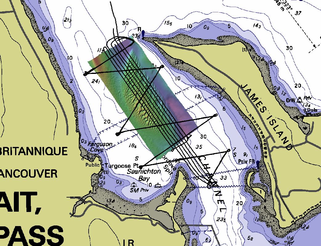
ADCP survey
experiment:
The Cordova channel has a well studied set of eddies that form on
both the flood and ebb tides. The net result is the formation, and
continual cyclic migration of the major banner bank between James
Island and the Saanich Peninsula (see figure below). We have
monitored this sand bank multiple times per year since 2011. And
archived CHS surveys exist of it from 1999 (EM3000) and 2013
(EM3002). There is a clear anti-clockwise residual circulation about
the bank, with the boundaries of the bank being very stable from
year to year. While the dunes move continuously, the dune character
(asymmetry, wavelength sinuosity) is very stable from survey to
survey. They must thus reflect the impact of the two eddies.
In order to prepare for a future 12.42 hour experiment, we set up
the 1200 kHz ADCP on a mount off the front of the pole on which the
EM2040P was installed., We then ran a series of transects across the
Cordova Channel, deliberately cutting across the banner bank (see
trackplot below). The aim is to see the evolution of the flow field
over the tidal cycle. And, as we are logging EM2040 and EM710
continuously, we can monitor whether the dunes are moving and, from
the water column, see when in the tidal cycle the sediments are
suspended.

|
 |
showing the survey design for
the ADCP experiment.
|
showing the logged data during
the flood tide for the ADCP experiment
|
The ADCP data were processed in a preliminary manner on board by Ian
Church. As this experiment only lasted 3.5 hours and was conducted
during neap tides, spectacular results were not expected. It is the
intent to build on this in following years.
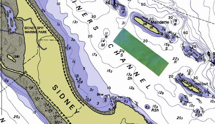
Robert Point Test Area
Located just seaward of the Sidney Marina, it has been used as a
test area since 2014. The Roberts Point location provides a wide
range of seabed types in the 13-34m range with lots of interesting
targets. It was expected that this area would be a lot more stable
than the Cordova Channel area. As it turned out, there is more
variability than expected.

location of Roberts Point test site relative to Sidney Marina
One of the main purposes was for assessing multi-spectral scattering
differences.
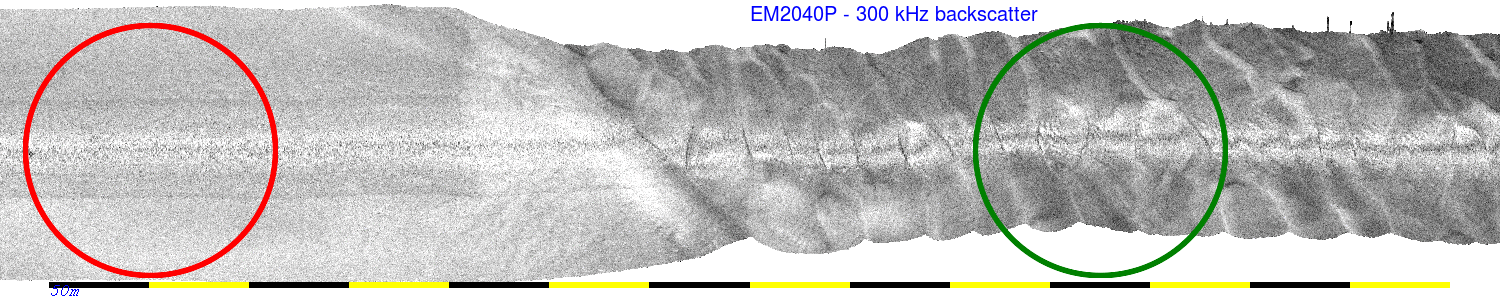
Multi-spectral Coverage
EM2040P bathymetry.
|
EM2040P - 300 kHz backscatter
|
EM710 = 90 kHz backscatter
|
|

|

|
This area was also subject to previous multi-spectral imaging
(710-2040C (200-300-400) in 2014, 2040D 200/300/400 in 2015).
Long -term it is hoped that inter-system calibrations can performed
be (using a reference dataset that we have yet to collect!).
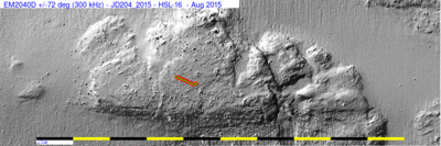
Comparison
of resolution with 2040C and 2040D
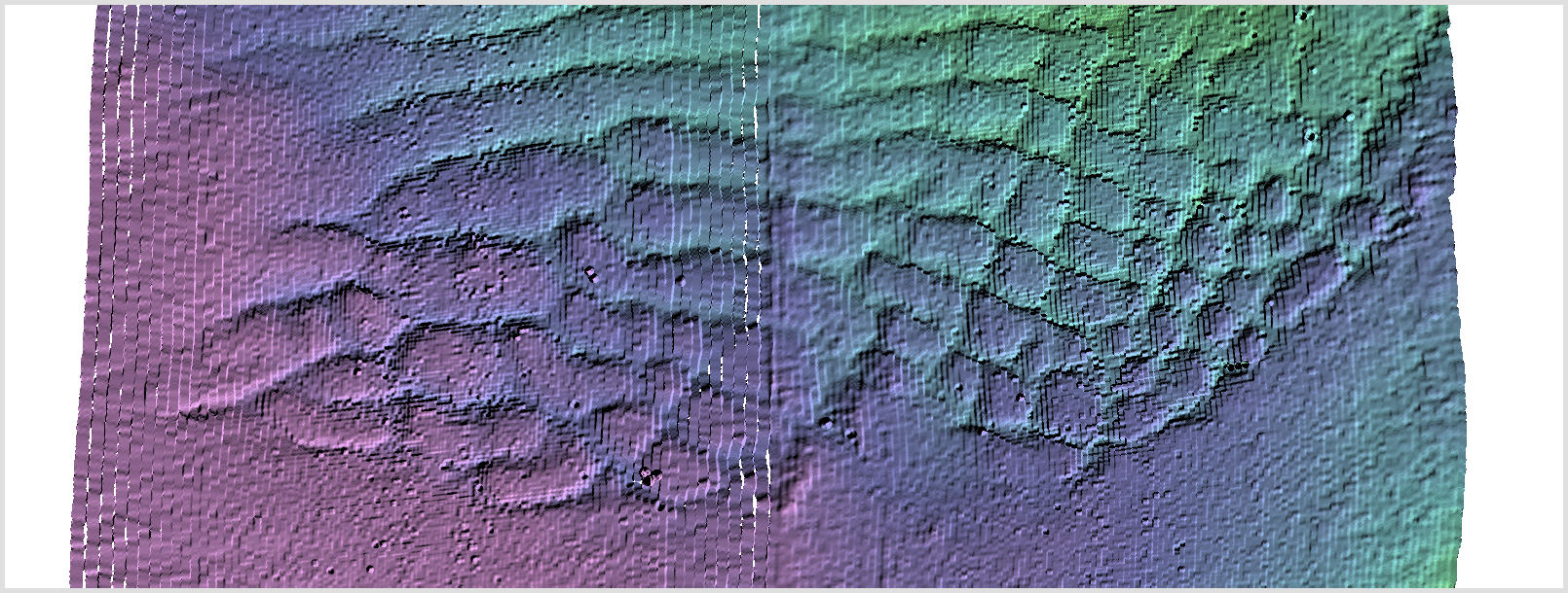
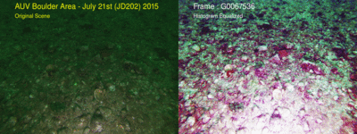
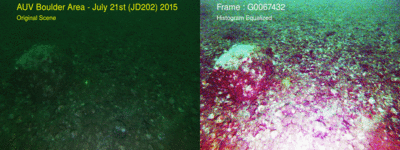
In the centre-left of the Roberts Point survey is a conspicuous
bedrock knoll, the top of which is covered with small boulders. It
has now been surveyed with all of a 2040C (single swath), a 2040P
and a 2040D.
 animation comparing 2040C - 2040P - 2040D over
the same boulder covered bedrock knoll
animation comparing 2040C - 2040P - 2040D over
the same boulder covered bedrock knoll
(colored line is the transect of the bottom camera - see
photos below).

|
|
|
2040C - +/-65 deg - 300 kHz
- 2014
|
2040P - +/-65deg - 300 kHz -
2018
|
2040D - +/-72 deg - 300 kHz
- 2015
|
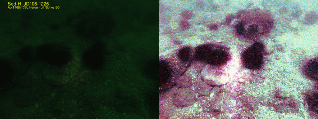
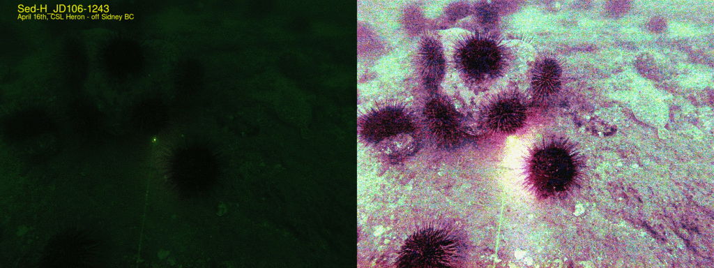
bottom photos obtained using a GoPro transect -
April 2015 (see map above for transect location)
as always - laser dots are 10cm apart.
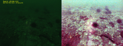
cobble pavement (with shell debris)
|

20-40cm boulders
|
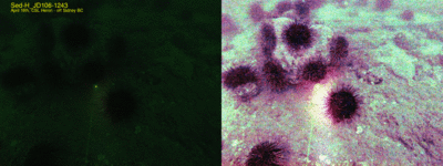
50cm wide boulder (colonized by urchins)
+ flounder!
|
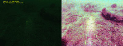
1m wide boulders
|
EM2040P Pulse lengths setting: all using the
0.101ms pulse
EM710 using the 0.16 ms pulse (Very Shallow)
Inter-year
Morphological Changes
It had originally been assumed that the Roberts Point area was
relatively stable. Unlike the Cordova Channel where actively
migrating bedforms were very visible, most of the morphology seen
from bottom photos showed a high extent of biological colonization,
suggesting that the sediment -water interface was stable.
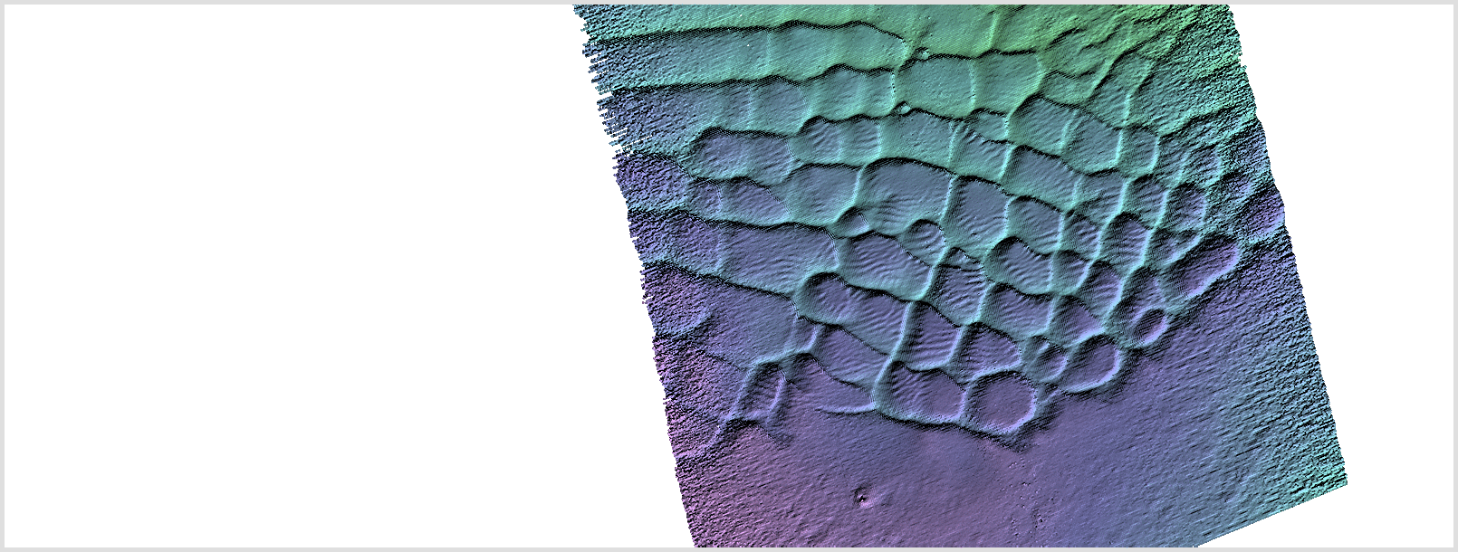
By comparing the 2014 EM2040C survey, with the 2015 EM2040D survey
and the 2018 EM2040P survey, however, it is apparent that in the SE
section of the region, the flute-like structures are actually quite
rapidly changing. The animation below illustrates the migration of
these bedforms over a 4 year period. NOTE that at this scale, and as
heavy (100%) swath-to-swath overlap has been used, there is little
apparent difference in resulting resolution of the C v. the P v. the
D. In all cases, the definition of the boulders in very clear.

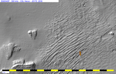
0.35m pixel grid of the fluted area
the coloured track is the bottom camera transect location (see
photos below)

|
|

|
2040C - 2014
|
2040P - 2018
|
2040D - 2015
|
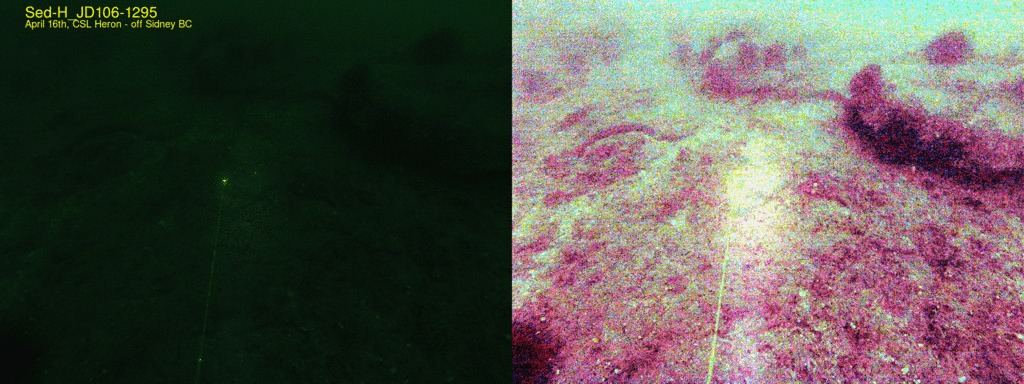
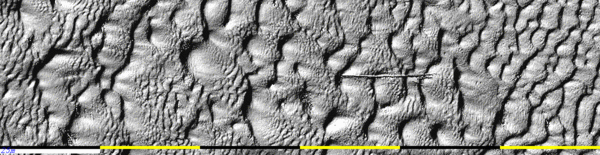
As can be seen from the scour moats around the large boulders in the
east side of the area, the residual sediment transport clearly goes
to the NE. The flutes are aligned with that transport path and
thus they are not conventional transverse bedforms.Flutes are
usually an erosive flow-aligned bedform. The bottom photos
(see below) suggest that the flutes are carved into a stiff
mud (possibly an over-consolidated glacial mud). The process
can't be happening that fast as the surface is extensively colonized
with small epifauna.
bottom photos (poor lighting conditions) showing
colonized - erosive muddy surface.
as always - laser dots are 10cm apart.
|
 |
 |
 |
 |
 |
closeup
fauna
(+drop-weight)
|
fana
|
ripples?
|
scour
around fauna
|
ripples and
fauna
|
ripples and
fauna
|
Ephemeral bathymetric roughness associated with weed
growth.
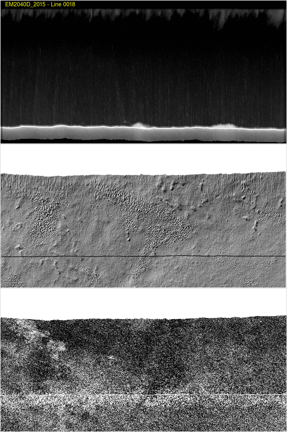
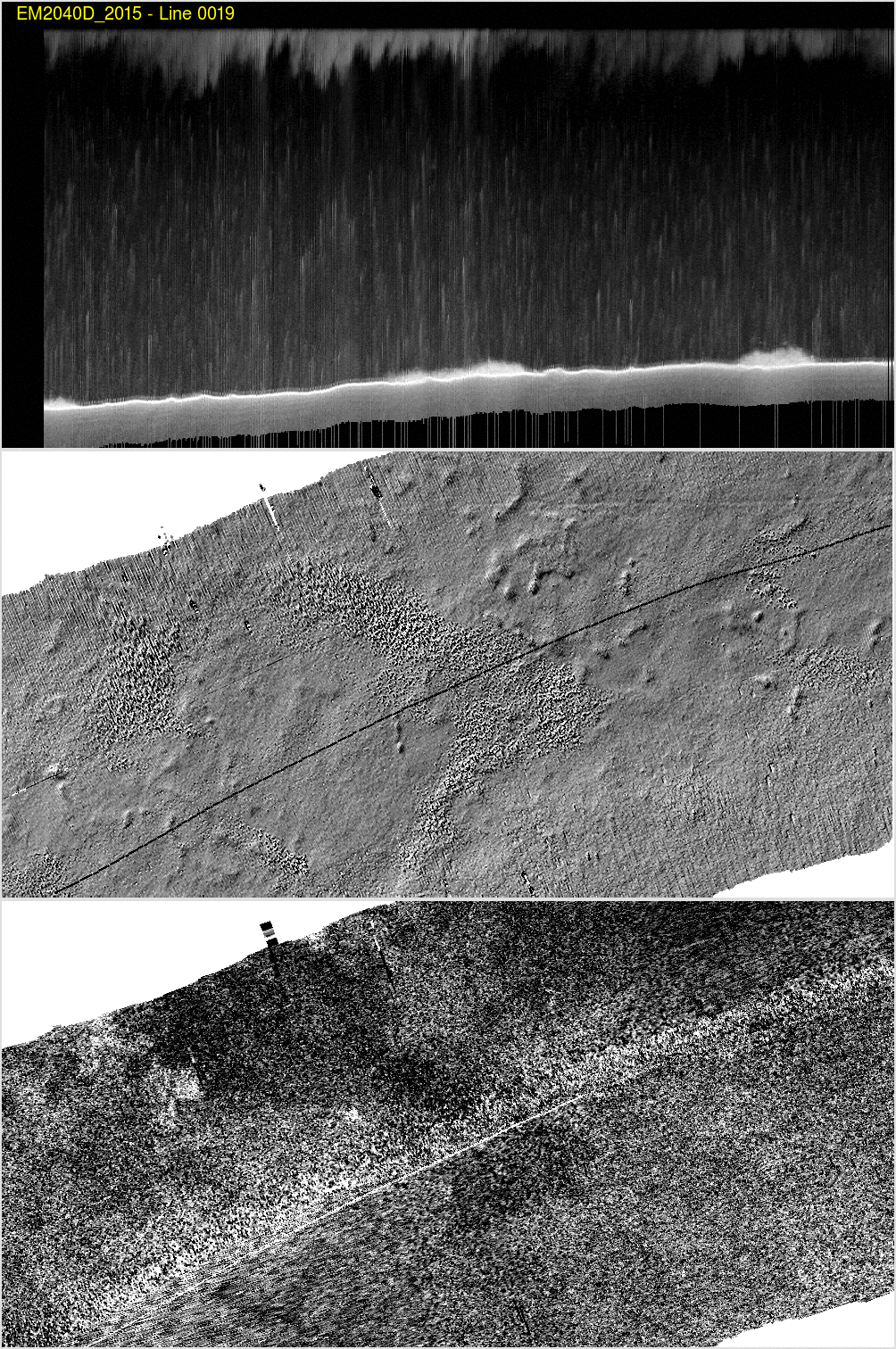
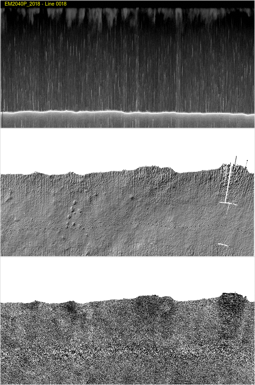
When comparing the EM2040D, EM2040C and EM2040P, it was expected
that seabed changes would reflect only the sonar capabilities.
However, as is apparent in the changing morphology, there are also
seasonal changes in the attached algal populations. The alternating
example below shows exactly this. Note that there are two
aspects:
- appearance and disappearance of zones of a fine roughness.
- appearance and disappearance of low, longer wavelength relief.
As it turned out (see water column examples below), the fine
roughness is related to the presence of sea-bed attached weed that
is about 1m high.
Showing the nadir water column section. Fro the 2015 surveys it is
clear that the bathymetric roughness corresponds ot presence of
algae that rise up from the seabed.
JULY/AUGUST - peak
seaweed growth
|
OCTOBER - seaweed
growth declining
|
EM240D - 2015 - Pass A
|
EM240D - 2015 - Pass A |
EM240P - 20158- Pass A |
EM240DP- 2018- Pass B |
|
 |

|
 |
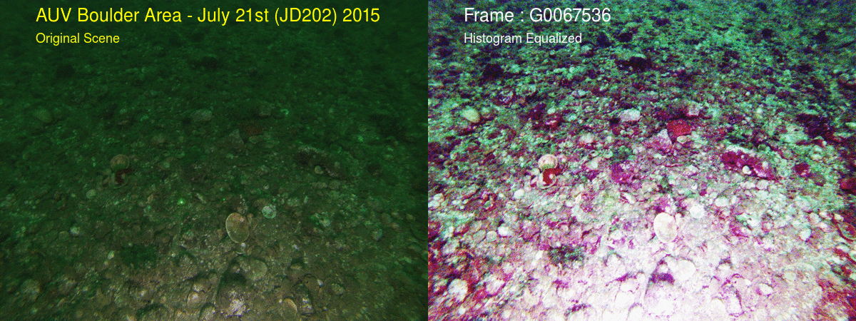
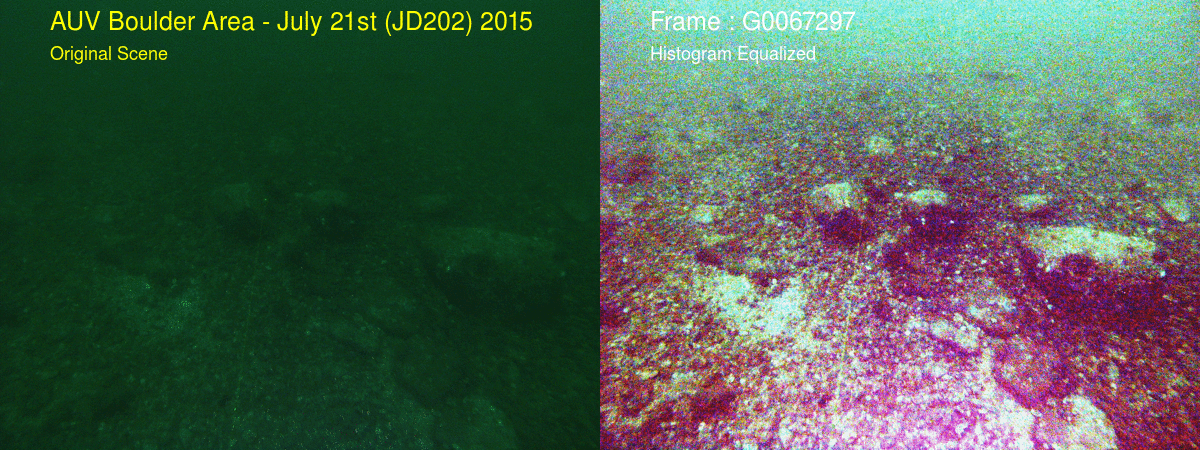
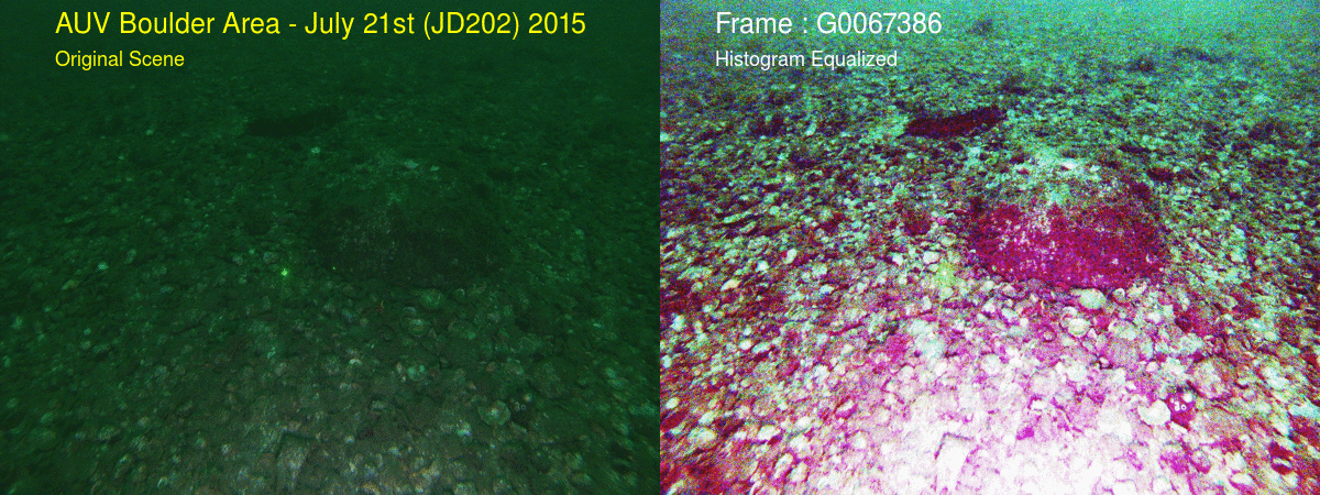
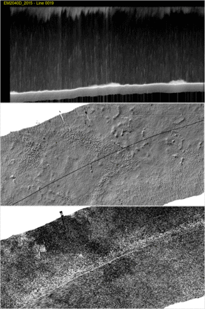
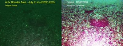
AUV Boulders
Area (Miner's Channel)
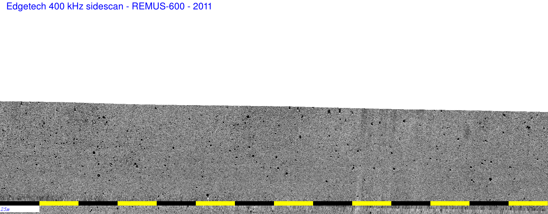
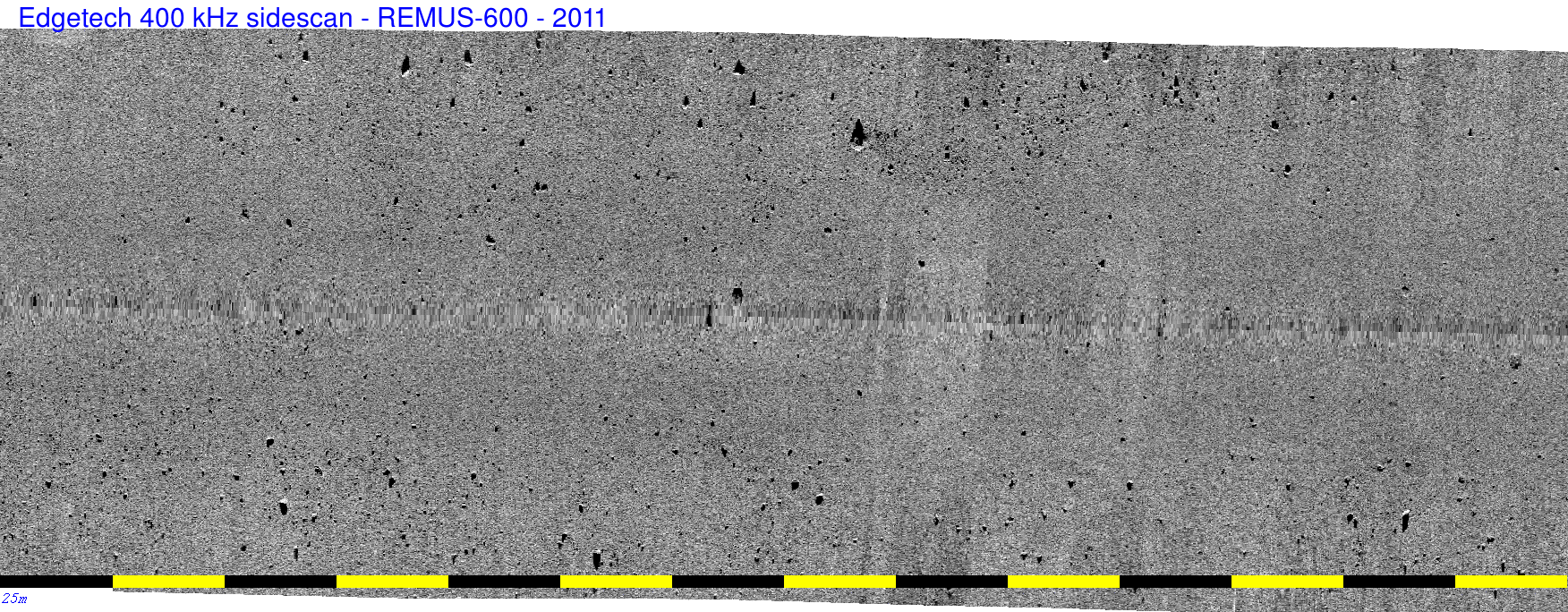
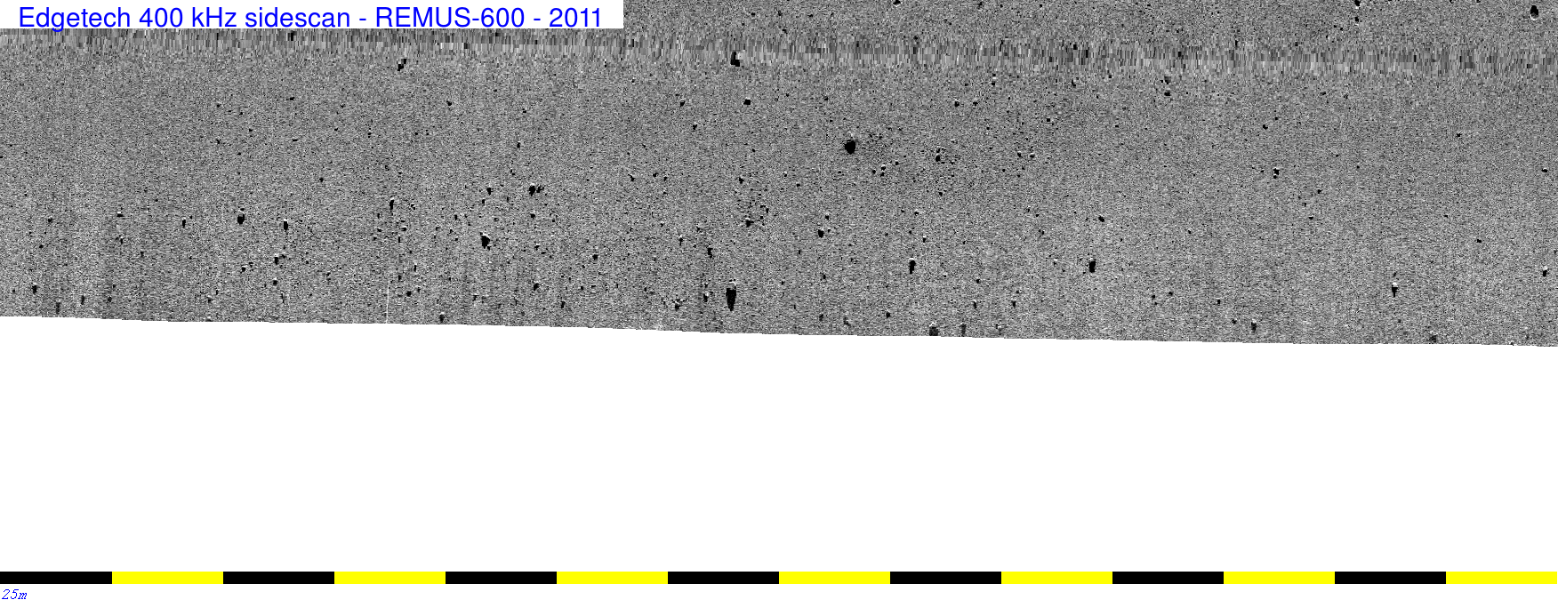
This site is our classic location for natural boulder detection. It
has been surveyed over the past 7 years as part fo the NAVOCEANO HSL
trials, including their HSL choices (EM2040S, EM2040D) and their
REMUS-600 with an EM3002 and an Edgetech sidescan. Following on from
that, the CSL Heron has been here many times with a variety of
sonars (EM710, EM2040C, M3).
 the standard "AUV Boulders" test area in Miners
Channel.
the standard "AUV Boulders" test area in Miners
Channel.
The seabed is extremely stable and is covered with a range of
boulders that have been well documented through the use of a towed
camera (see below):
close up showing the mollusc-colonized
gravel pavement
|

field of boulders - ~10-20cm wide
|
solitary boulder - ~50cm wide
|
solitary boulder - ~40cm wide
|
for all bottom photos- the two laser beam dots
are 10cm apart.
Warrior Point
Concrete Targets
While usually we run lines over the Warrior Point concrete
cube range, this year it was found that the oceanographic conditions
were unsuitable for working there (extreme and undulating
near-surface thermocline). This has been an ongoing issue with the
NAVO testing. It would be ideal to collect data there before the
summer thermocline develops (as was the case for the 2040C data).
Race
Rocks Operations
Operational Area
In 2011, as part of the original NAVOCEANO trials, we arranged to
have the 2040S deployed to the Race Rocks area (see figure below)
which lies ~ 10 miles SW of the mouth of Victoria harbour. This was
for two reasons - highest likelihood of getting significant sea
states (swell does leak in from the Strait of Juan de Fuca), and the
fact that it is a known highly dynamic seabed. Additionally, in
2009, the CCGS Vector, using an EM710 0.5x1, serendipitously picked
up strong internal waves in that region while transiting through.
Conveniently the whole area is already well surveyed by the CHS as
part of their regional coverage (primarily CCGS Vector EM1002 -
2003-2008) and thus the location and extent of active sand wave
fields is well known.
For the 2040P trials, there were four objectives:
- compare bathymetric performance in 100m of water to the
0.5x1.0 EM2040S (collected in 2011) and the 0.5x1.0 EM710
(collected in 2009)
- see what effect pulse length settings have on the resolution
of the 2040P in these water depths.
- collect bi-spectral (710 and 2040P) data over the sand
wavefield.
- see what the 2040P water column imaging looks like in the
area of dynamic oceanography.
(and -not-so-secretly - 5 - try to better understand the
origin of these enigmatic bedforms)
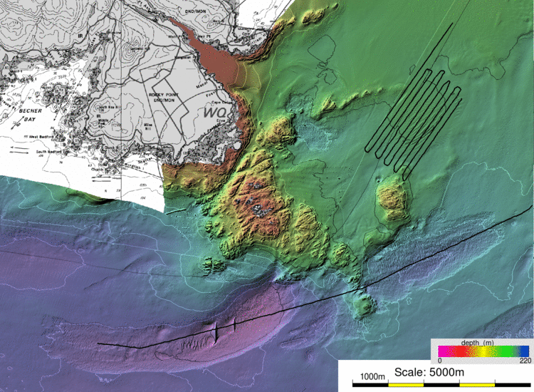
location map showing the sand wave field and the transect over the
rock ridge.
The Race Rocks headland acts to constrict and accelerate the tidal
flow as it comes to/from the Strait of Juan de Fuca. The currents
are strongest through the topographic restrictions around the
islands themselves. The scour depressions are best developed
in the deeper water off the SE tip of the rock ledge. And it is that
flow that is perturbed by the rock ridge (see later internal wave
study).
The sand wave field are in the flood tide lee, NE of the Race
Rock shoals.
The following 2040P analysis results were obtained:
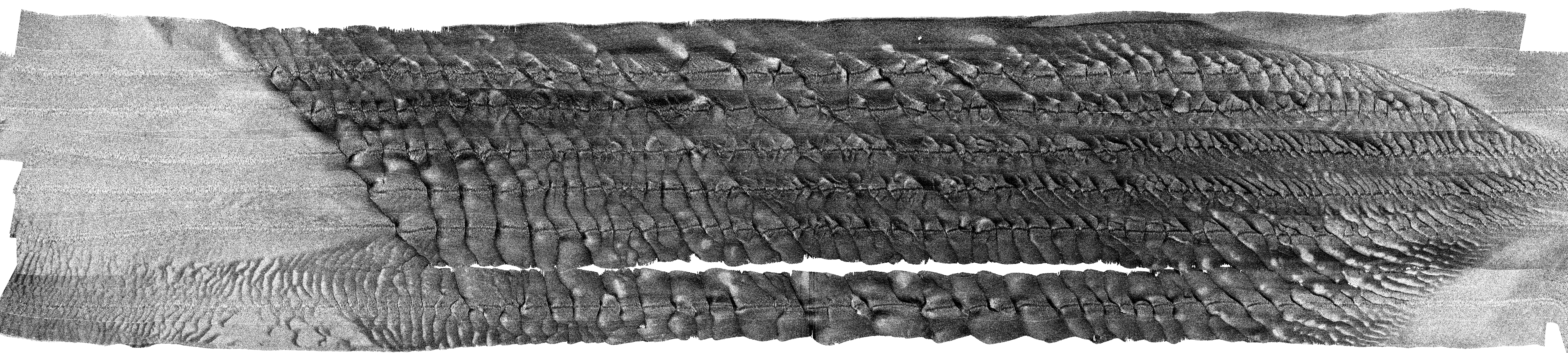
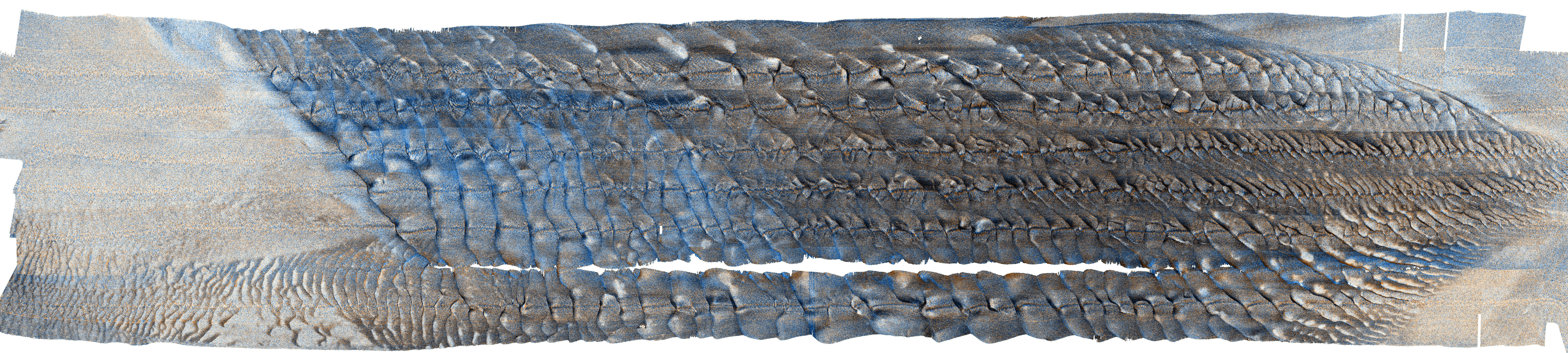
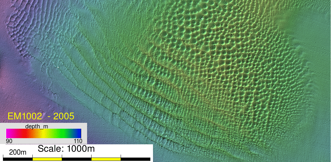
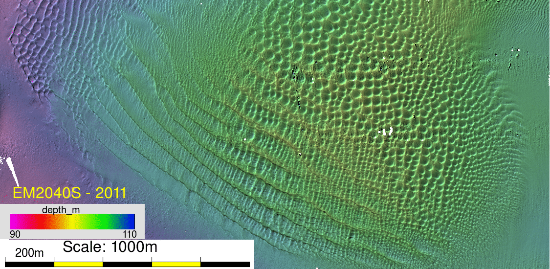
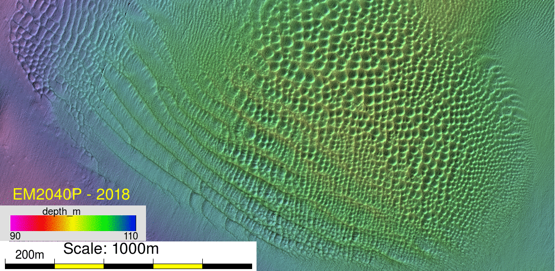
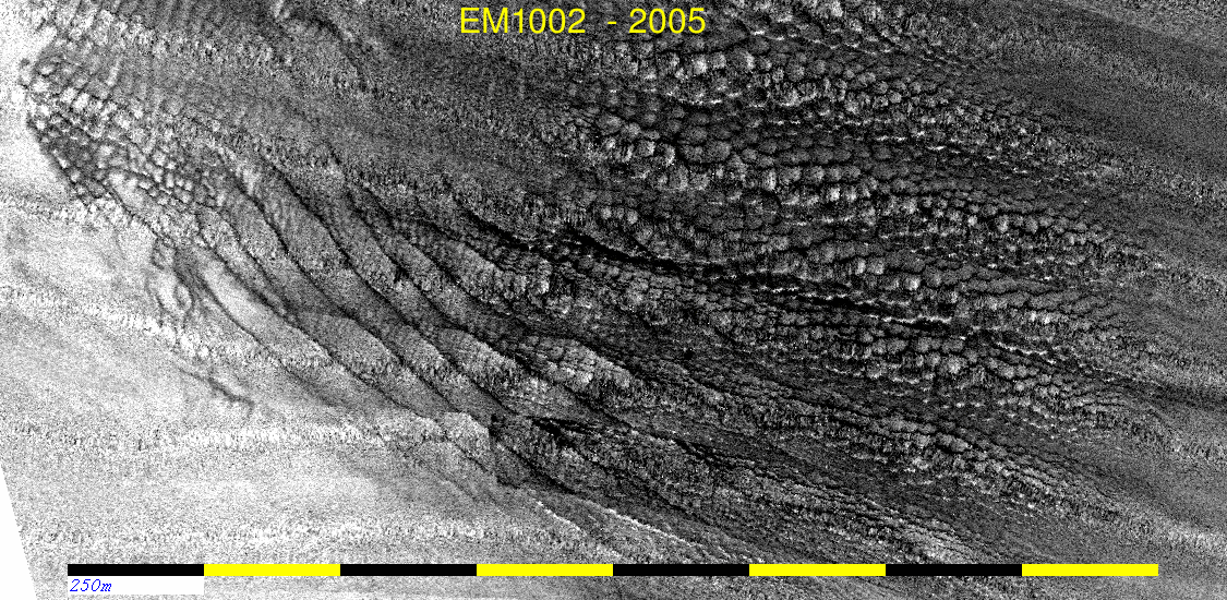
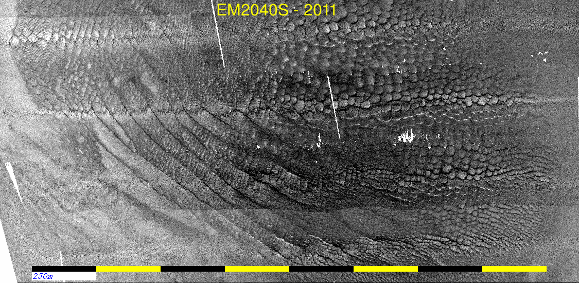
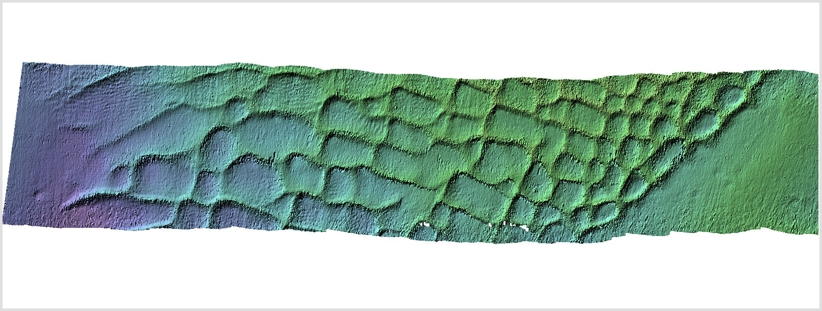
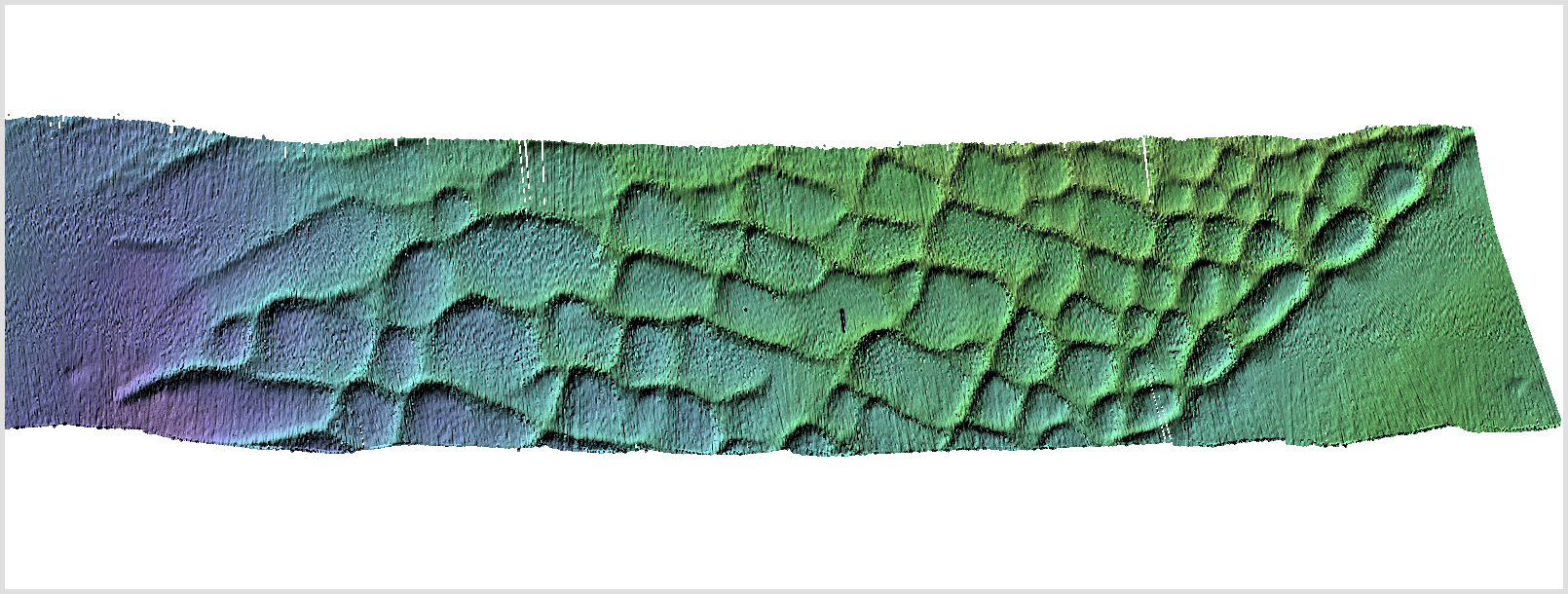
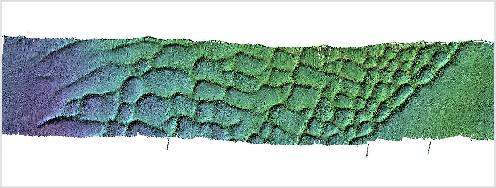
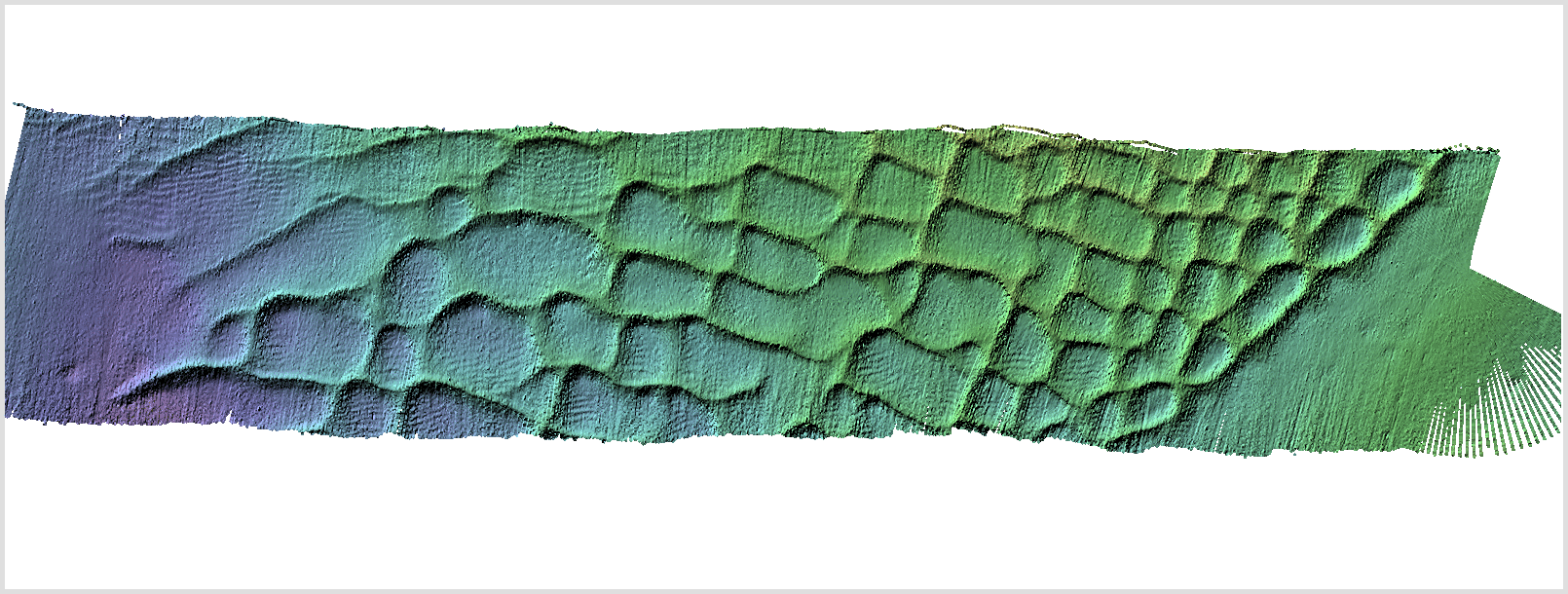
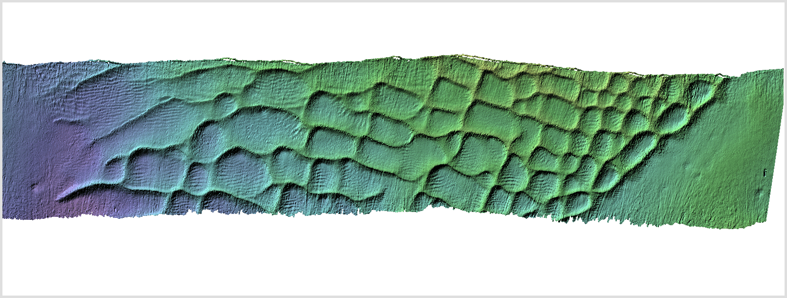
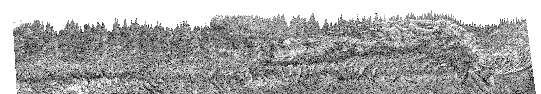
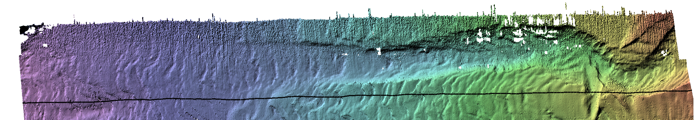
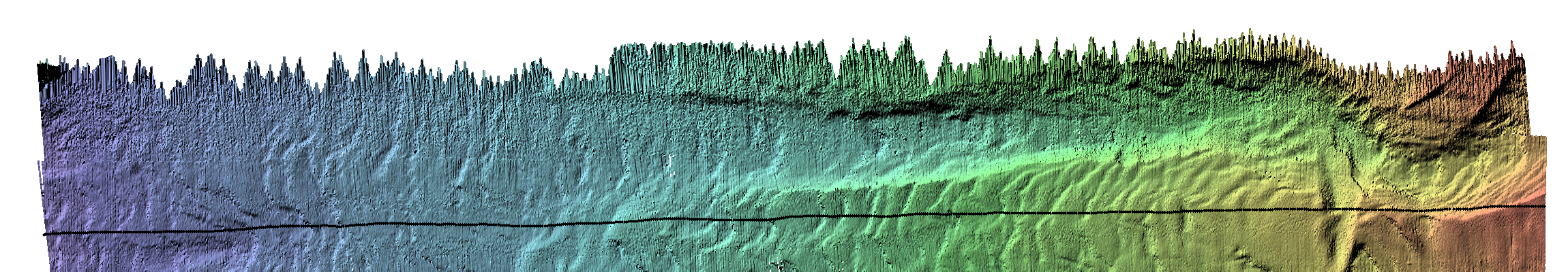
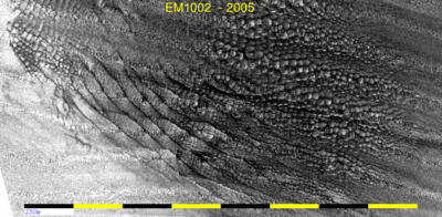
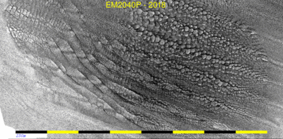
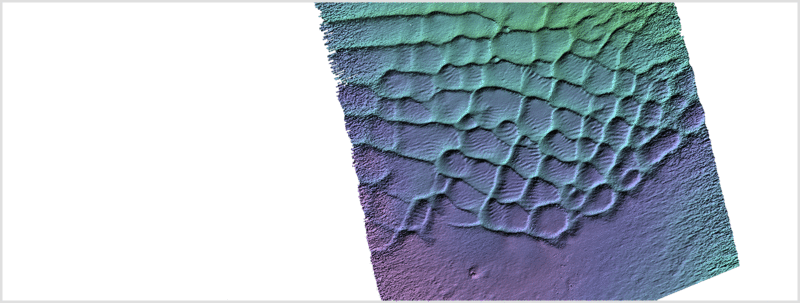
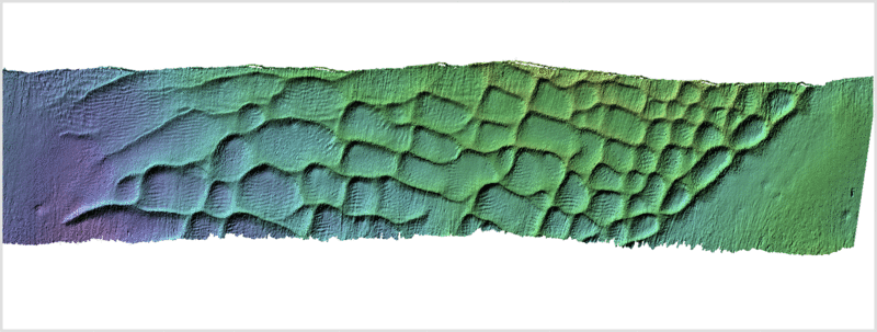
SnakeSkin sand wave
field
An amazing sand wave field exists NE of Race Rocks (see survey track
pattern in regional map above). It is spatially constricted and
consists of a unique pattern of bedforms. There appear to be two
patterns superimposed coming from different directions. The net
result is an amazing "snakeskin" pattern. And it is not static,
continually changing from year to year. We now have 3 passes over it
(2005, 2011 and now 2018). This both provides an indication of the
stability of the field (the types of bedforms and the boundaries
between them) and the relative ability of differing sonars to
resolve these short period roughness features.

animation comparing the three surveys of 13 years. - 2m resolution
data (in ~ 100m of water)
EM1002 - 2005
|
EM2040 (0.5x1.0) - 2011
|
EM2040P - 2018
|

|
 |

|
|

|
|
This year we were able to add the EM204P to the surveys and
both compare its performance relative to other sonars, and to get a
bi-spectral view of the associated backscatter. The figures below
show the same seabed, as seen at ~ 70-100 kHz and 300 kHz. As
with the previous examples, we provide a bi-spectral image that
highlights where the frequency responses are notably different.
EM2040P bathymetry
|
EM2040P 300kHz
backscatter
|
EM710 100 kHz backscatter
|
red (100 kHz) blue (300 kHz)
composite
showing frequency dependences
|
 |
|
|
|
|
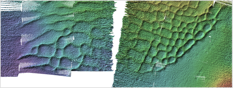
From the point of view of bathymetric resolution, two areas
were of interest:
- The NW flank of the field where 4 generations
of EM systems have run over the same seabed.
(black box on map to left)
- The Southern toe of the field which had a
unique ripple pattern within the dunes that is at the
limit of resolution.
(white box on map to left)
results are presented below...
|
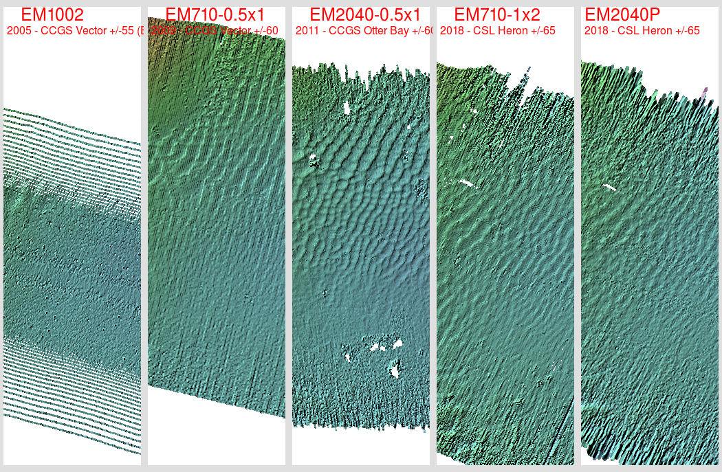
The NW flank -
4 generations of EM sonars.:
Here we compare the near same location as seen with a single
swath of all the different sonars utilized. For this particular
line, the EM1002 was operated in equi-angular mode, although about
1/2 the survey in the area used EDBS. The narrow beam 710 is
only operating in single swath mode (the dual swath capability
wasn't functioning at the beginning of the trials in 2009).
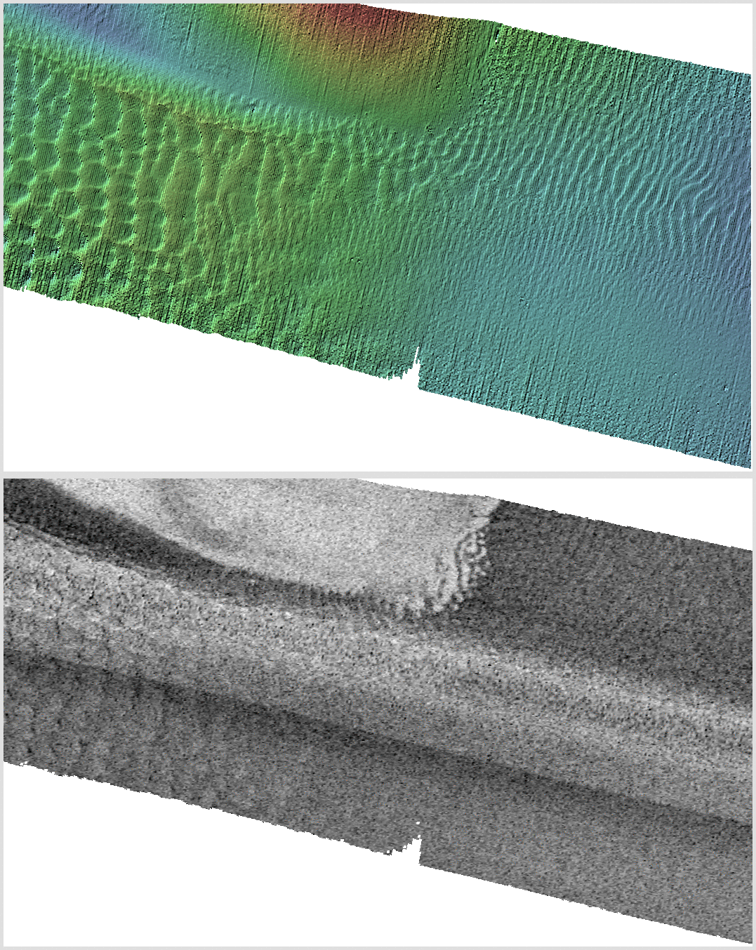
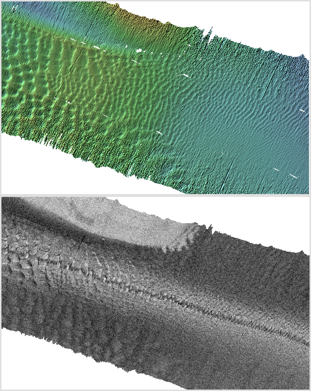
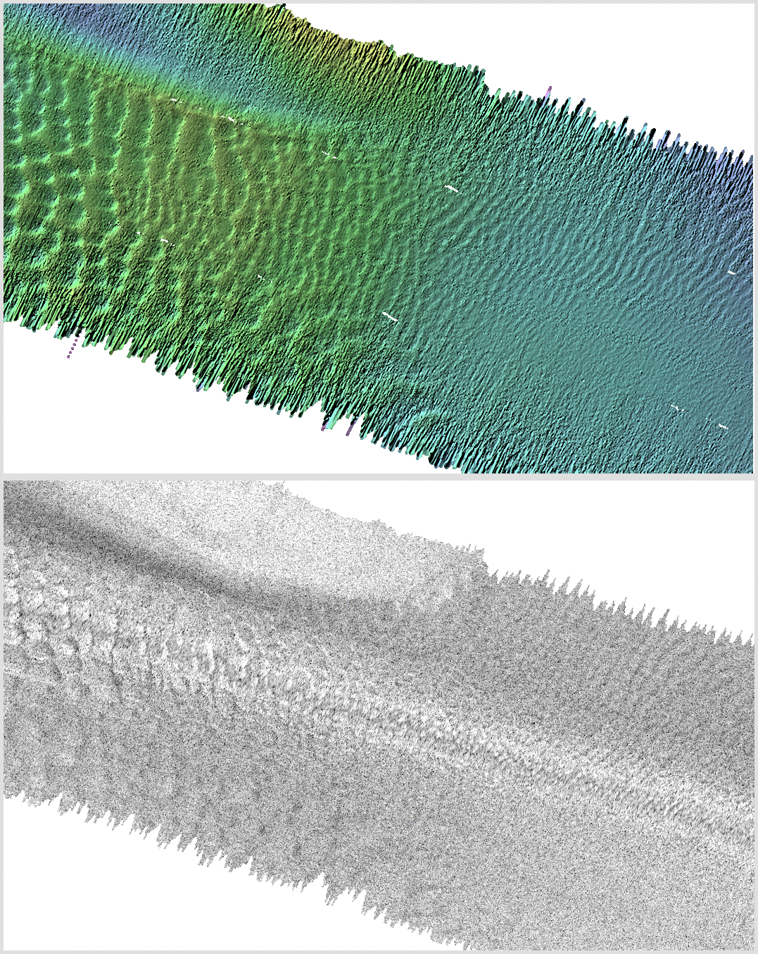
EM1002
EquiAngular +/- 55°
CCGS Vector
2005
|
EM710 0.5x1
HDBF +/-60° - Single Swath -
2.5 Hz
CCGS Vector - 9.7 knots
2009
|
EM2040S 0.5x1.0
300 kHz° +/- 60°
CCGS Otter Bay
2011
|
EM710 1x2
Shallow Mode +/-65°
CSL Heron
2018
|
EM2040P
300 kHz +/-65°
CSL Heron
2018
|
|
|
** mistracking due to dense
mid-water fish schools
|
|

|
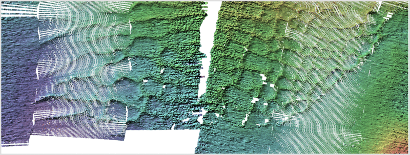
Notice that the two 300 kHz versions of the same area have a
notable higher backscatter strength for the fine grained material.
In all cases, no post-acquisition beam pattern corrections have been
applied.
To highlight the relative resolution, the following images are picks
out a slice from each at 0.75 m pixel resolution.:
Definition
of fine-scale morphology in 100m of water.
Within the rhomboidal bedforms on the southwest end of the sand-wave
field, there are a clear sub-population of ripples. This was
serendipitously discovered in 2011 when the EM2040S (0.5-1.0) was
being tested by NAVOCEANO . The system was mounted on the CCGS
Otter Bay and this area was originally visited purely because it can
be partly exposed to open ocean swell.
Quite by chance, the vessel logged data (300 kHz - pulse length XXX
- +/- 60 deg at 5 knots) over the bedform field.
What was previously know
(2005):
EM1002
2005
(CCGS Vector)
~2°x2°
+/-60
2 Hz
6.8 knots
2 N-S passes -
- leftmost EA
- rightmost EDBS
|

no indication of the smaller population of bedforms
|
The benchmark to beat
(2011) !!
EM2040S
0.5 x 1.0
CCGS Otter Bay
NAVO trials 2011
5 knots
5 Hz
dual swath
+/-60 deg
optimizedline (artificially short pulse)
0.145 ms CW (10000 Hz BW)
|
clear indication of the smaller ripples
|
How a 2040P in auto
(+/-65 deg) mode performs:
EM2040P
regular line spacing
400 beams across
4Hz (dual swath)
2ms FM pulse
|
2040P operated conventionally (+/-65 deg, FM pulses) - no
indication
|
And the standard Heron
EM710 (1x2)
EM710
regular line spacing
Shallow Mode (0.5ms pulse)
200 beams across
(as 2 deg receiver)
4 Hz (dual swath)
0.5 ms (Shallow Mode) pulse
|
EM710 (1x2) operated conventionally (+/-65 deg, Shallow
Mode) - no indication
note as a 2 deg. receiver, there are only 200 beam across
track, hence the lower apparent resolution
|
So how can we do better?
- Pull in the swath
- Force to shorter pulse lengths
First try the 1x2 EM710
|
EM710
1x2
Shallow
Mode
0.5ms pulse
+/-30 deg
1300 rpm
(6 knots)
|
with a narrow sector, but still the 0.5ms pulse (Shallow
mode), things still don't appear
|
EM710
1x2
Very Shallow
Mode
0.2ms pulse
+/-30 deg
1300 rpm
(6 knots) |
switching to the 0.2 ms pulse (very shallow mode), they
just start to appear.
|
Now try the EM2040P
|
EM2040P
1.3°x1.3°
Very Deep
Mode (the default)
2ms FM pulse (1675 Hz BW)
+/-30 deg
1300 rpm
(6 knots)
|
narrow sector, but the default FM pulse for these depth -
not visible.
|
EM2040P
1.3°x1.3°
Deep
Mode
0.865 ms CW pulse (1661 Hz BW)
+/-30 deg
1300 rpm
(6 knots) |
switching to long CW (same bandwidth as FM) - still
not visible.
|
EM2040P
1.3°x1.3°
Medium
Mode
0.288 ms CW pulse (5000 Hz BW)
+/-30 deg
1300 rpm
(6 knots) |

now medium CW pulse - starting to be visible.
|
EM2040P
1.3x1.3
Shallow
Mode
0.101 ms CW pulse (14000 Hz BW)
+/-30 deg
1300 rpm
(6 knots) |
and finally, forced to short CW pulse, they appear
(still not as good as the full 0.5°x1° 2040 with a wide
sector though!).
|
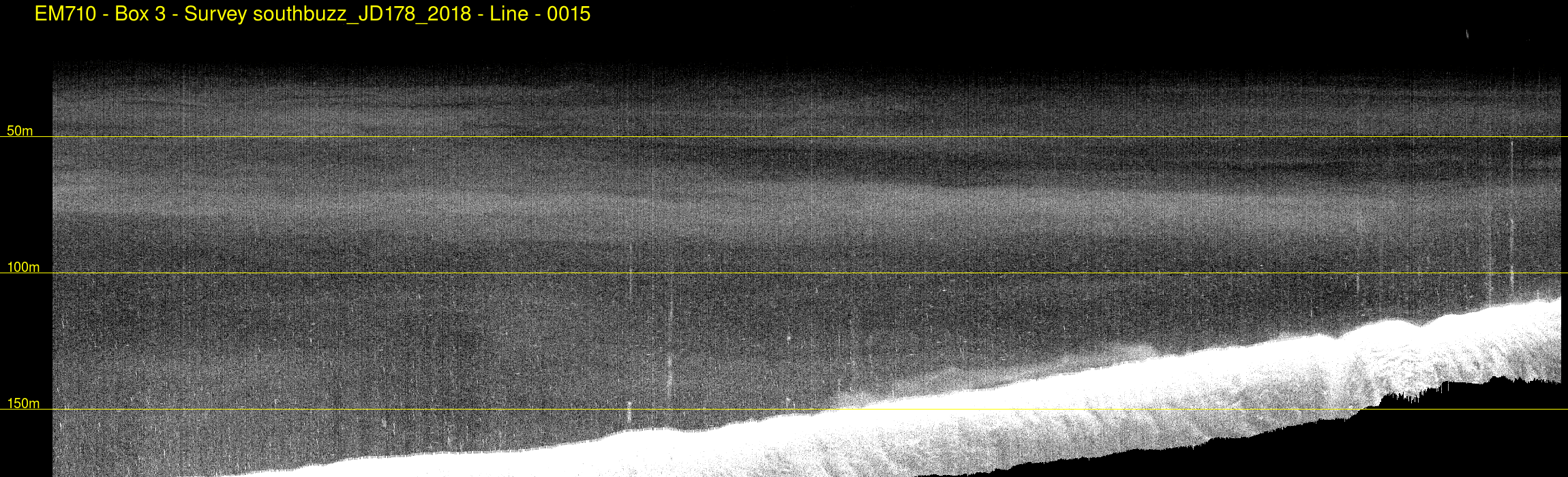
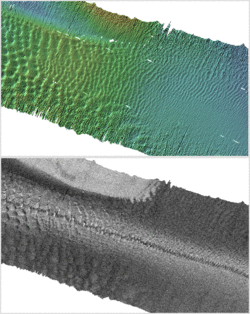
Race Rocks Ledge
Internal Waves
In 2009, as the CCGS Vector was passing Race Rocks during her EM710
acceptance trials along a serendipitous transit line, the logged
water column revealed that clear Kelvin Helmholtz waves were being
developed on the flood tide as the flow passed over the rock ledge
that runs SE offshore from the Race Rocks Islands (see regional
figure above).
It was felt that it would be of interest to see if those
oceanographic features could be recognized again, this time imaging
steaming slower and using multiple frequencies (710 and 2040) and
while simultaneously running the MVP to understand the oceanography.
Thus a single line was run that follows the main scour depression on
either side of the rock ridge. The line was run during the flood
tide.
The main bathymetric transect, and the two co-registered EM
water column sections are presented below:
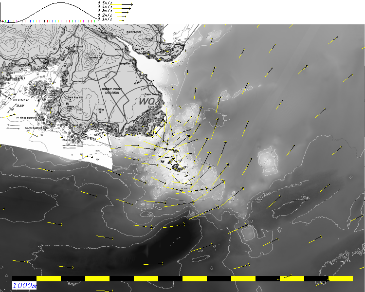
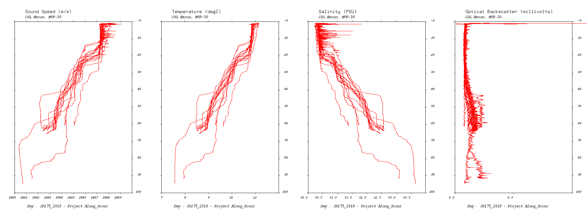
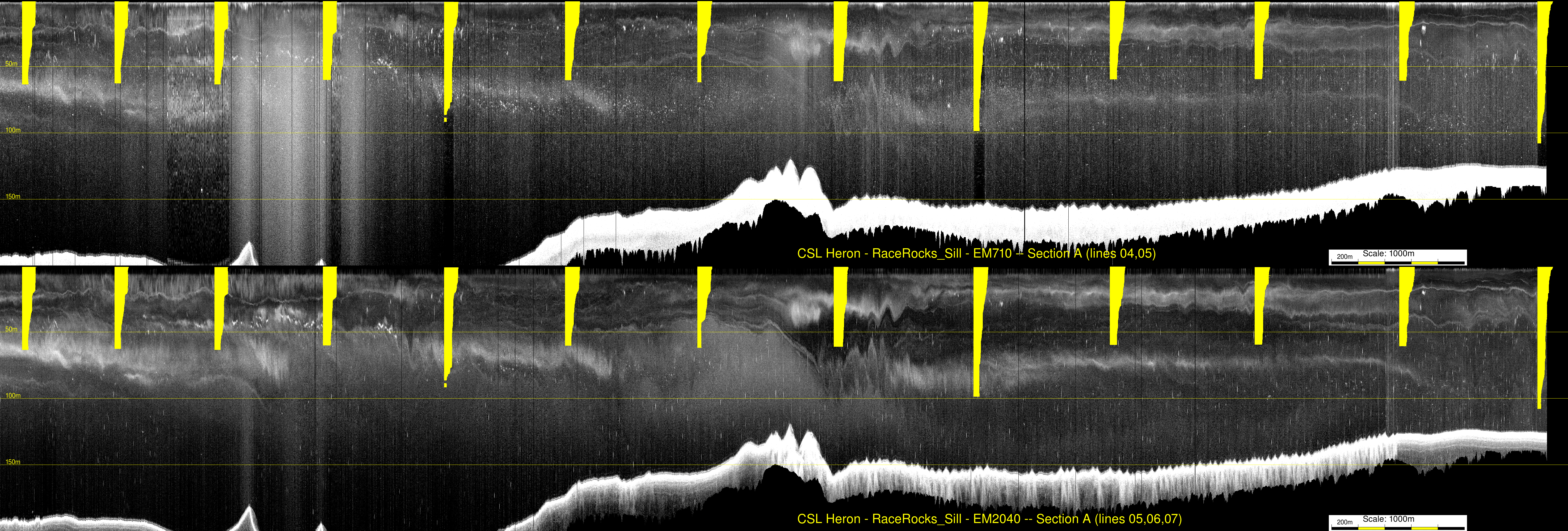
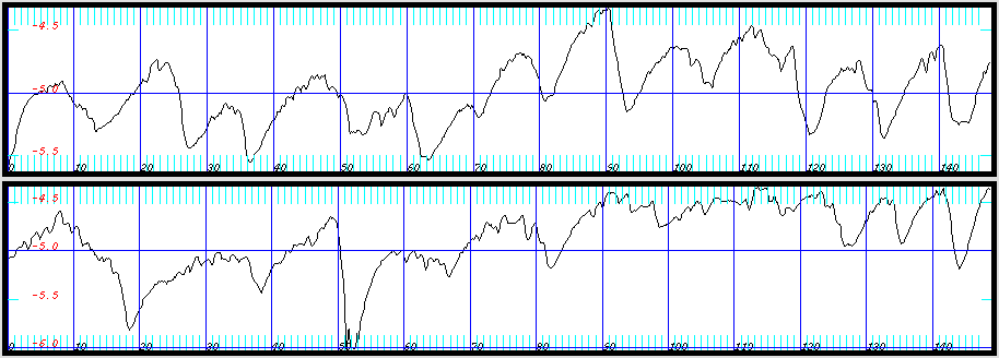
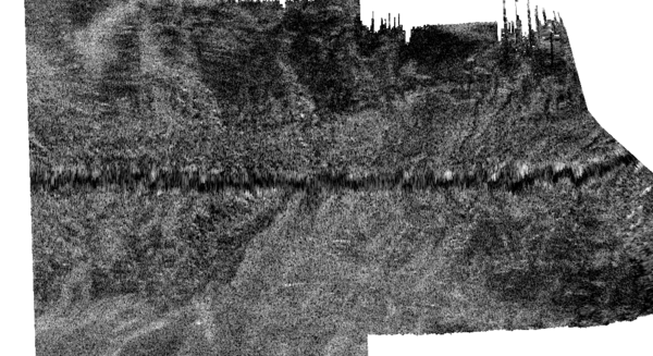
MVP sections:
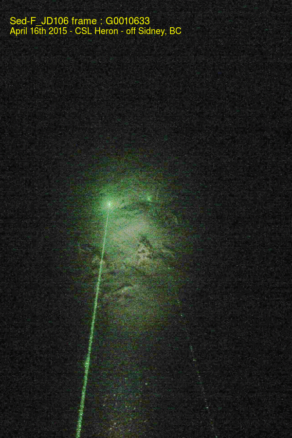
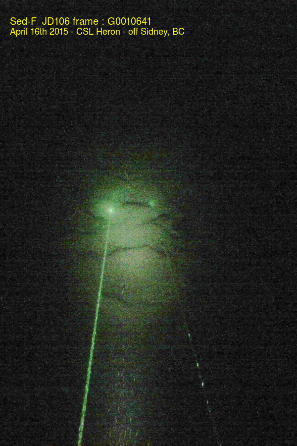
The MVP was run continuously dipping to ~ 60m depth. The hope was to
recognize the changing T and S structure at the various water mass
boundaries. As can be seen there are several clear steps in the
oceanography.
They then need to be plotted over the corresponding EM water column
imagery to see if they correlate with the observed scattering
layers.
The MVP over the main section looks like this (click for high-res.
view):
The animations below look at the across track structure as
you go over the sill. Not as exciting as I'd hoped, but then it
isn't spring tides.... Would have been nice to have the ADCP
running too, although the 1200 kHz will only see the top 20m (a 300
kHz would be ideal). As can be seen there is a lot more noise in our
EM710 (clearly correlated with prop. RPM). At 300 kHz, this noise is
not an issue.
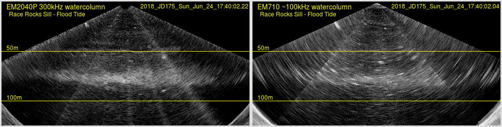
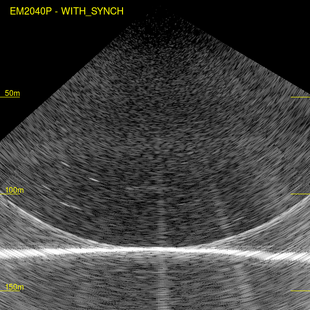
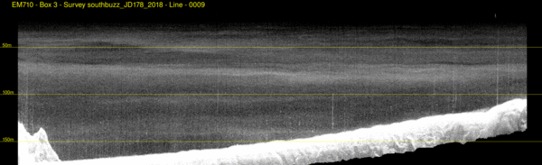
Synchronized Frames (even though the sonars weren't)
4.5 second averaging (~ 11 frames)
|
EM2040P water column
notice that the 2040 has a lot less noise
- just the 710 interference as unsynch'ed
|
EM70 water column
notice that the 710 appears a lot noisier
it is clearly more susceptible to propeller noise
|
Squamish
Operations:
Operational Area:
The Squamish prodelta is a region at the upper end of Howe Sound
that extends from the river mouth to ~230m depth ~ 10 km away.
It is routinely resurveyed by the CSL Heron using her EM710 about
3-5 times per year as part of a long term project that has been
running since 2006. The scientific aim has always been to look at
the movement of sediment off the delta into the deep water along
turbidity current channels that extend over 8 km from the river
mouth into depths > 200m.
As well as addressing sediment transport issues, however. Such a
depth range and such extreme sound speed changes (the river mouth
and plume) allows one to test out the sonar performances over
a particularly wide range of conditions. This summer (June 2018), we
had an EM2040P for the first time and wanted to compare its
performance against the EM710 from the ridiculously shallow (3-5m in
the river) to 200+m where the 2040P would, of course, be attenuation
limited.
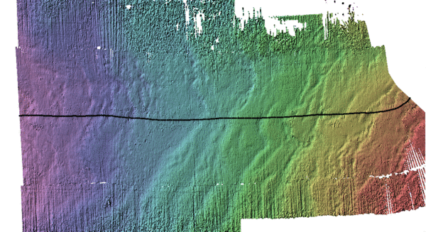
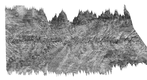
 showing the data acquired with the EM2040P.
White contours are the 100 (left) and 200m (right), black
contours every 10m. River mouth to the left.
showing the data acquired with the EM2040P.
White contours are the 100 (left) and 200m (right), black
contours every 10m. River mouth to the left.
We performed the following range of tests.
DeltaTop in 3-6m depths..
This isn't honestly a particularly fair test. However, we have
standardly done this range of depths with our EM710. We have also
covered the area with the EM2040S (05x1.0) in 2011 as part of NAVO
trials and the M3 in 2013 and 2015.
Improved
delta-top bedform imaging:
All surveys usually utilize the EM710 on board the CSL Heron. This
sonar (70-100 kHz) is really designed for ~20-1000m depths and thus
is optimal for the deeper fjords. While it does still operate in
shallower waters, it is not, however, optimal for depths less than
~10m. Nevertheless, as it was all we had, we have always used it for
surveying the ridiculously shallow waters of the delta top (3-6m
deep at high tide (~4m above CD).
In 2018, however, we were fortunate to be able to borrow an EM2040P
(200-400 kHz) and used it simultaneously to image the delta top in
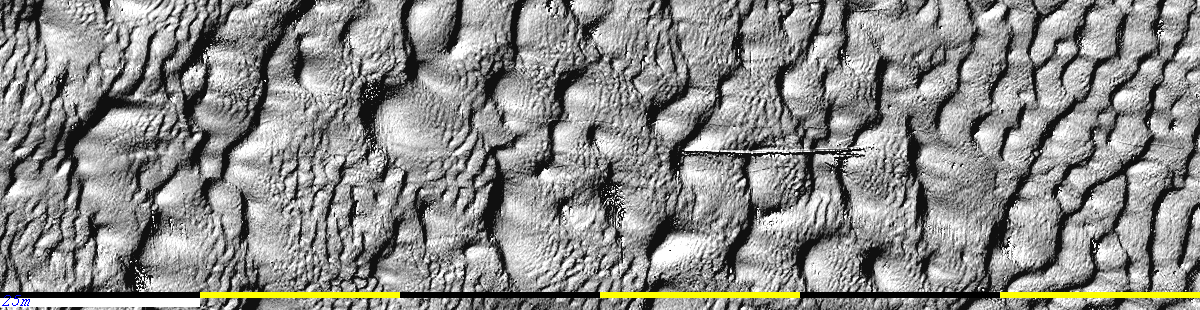
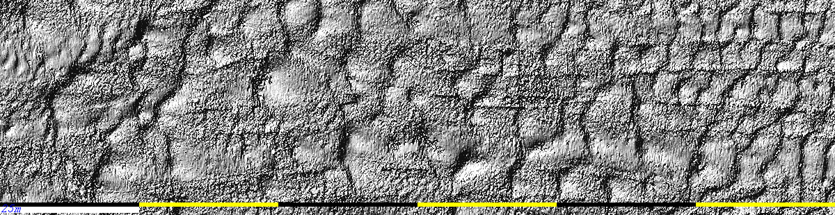
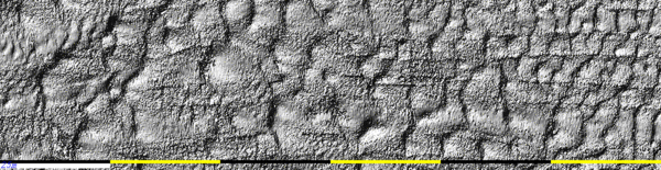
late June. The improvement in resolution is illustrated below:
Note that, when reduced to a 1m grid, there is little apparent
difference in morphological definition. At such short ranges,
however, the ability to resolve decimetre wavelength bedforms is of
great value.
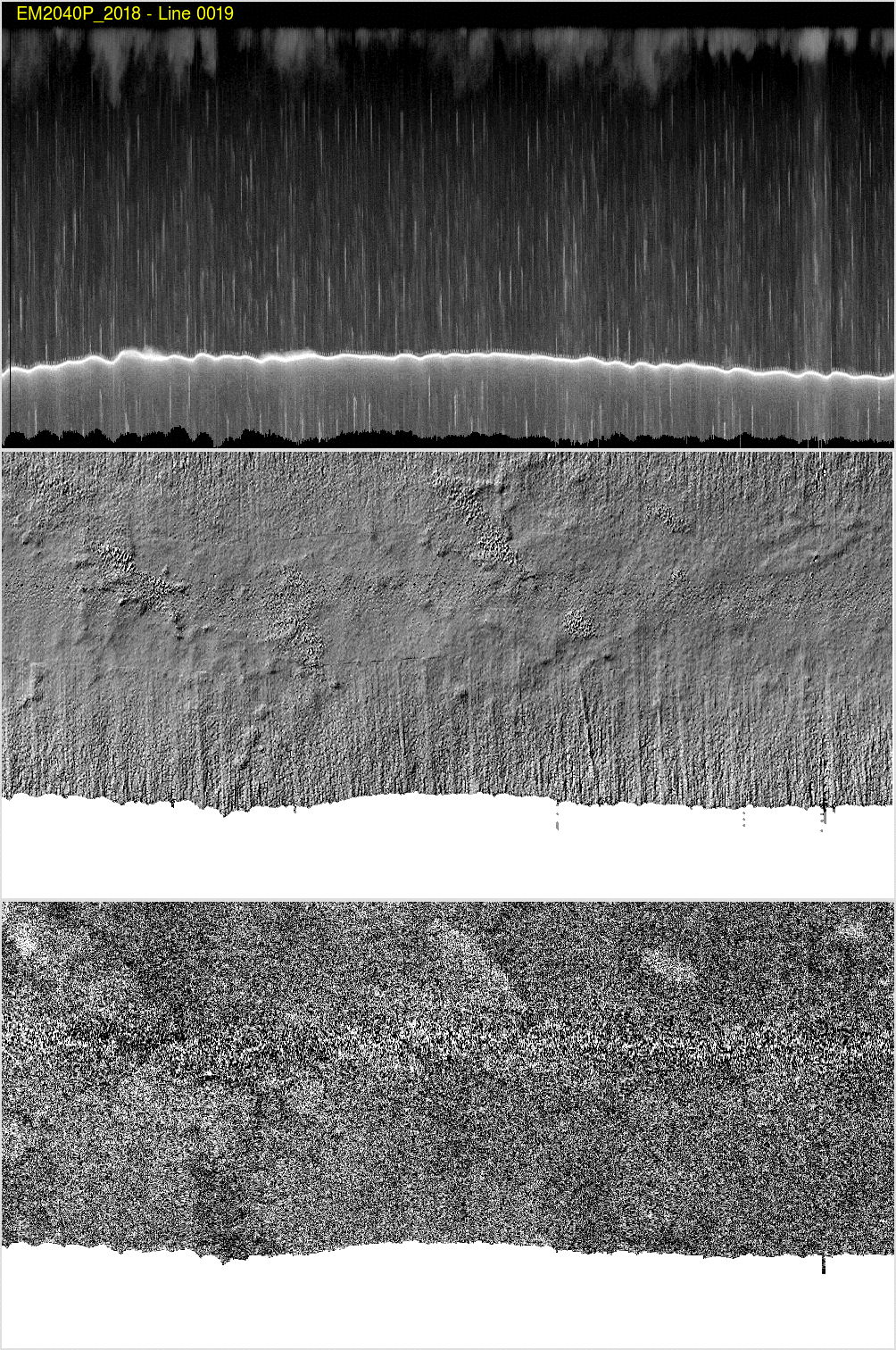
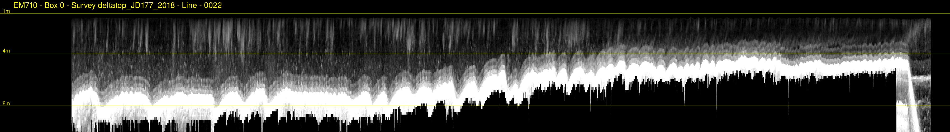
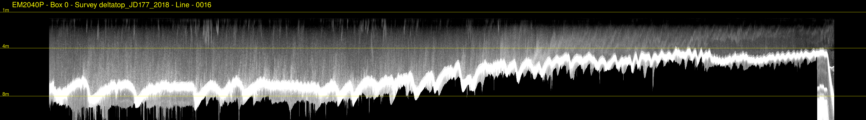
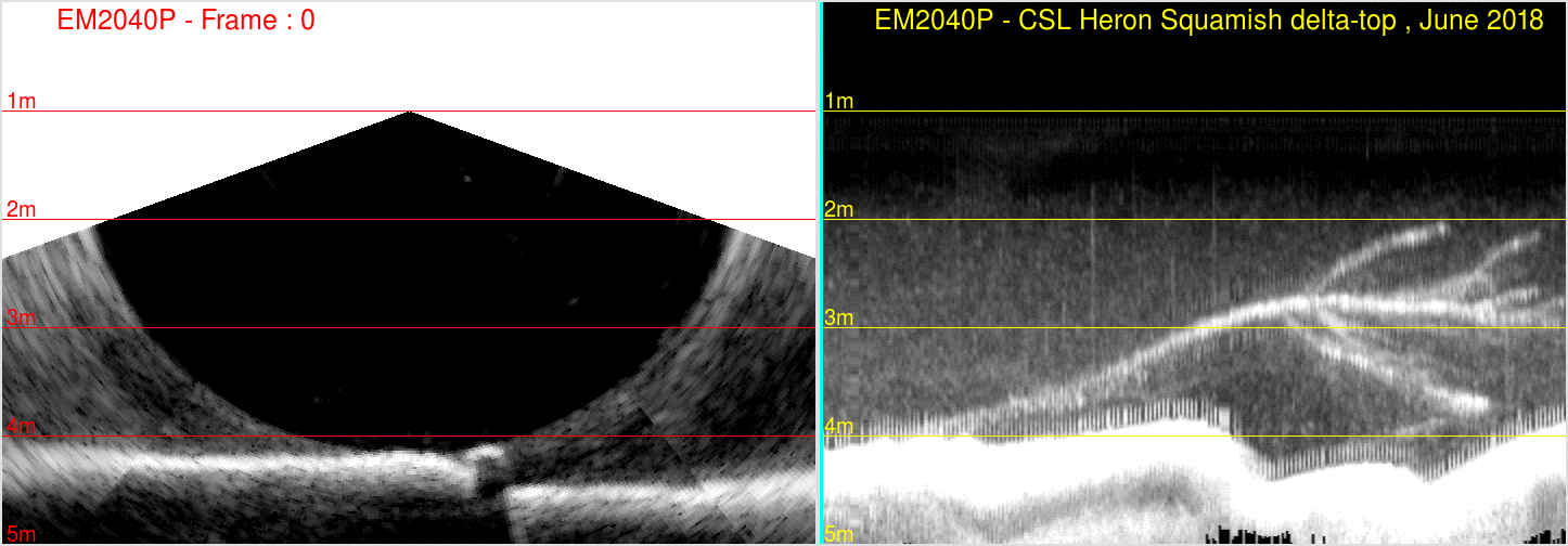
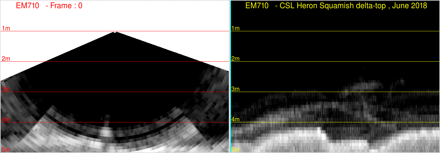
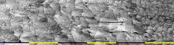
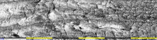
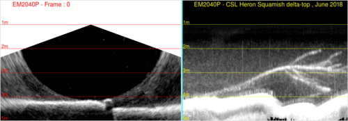
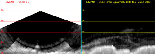
Water Column
Imaging in 2-5m depth
We have a long tradition of running the MVP along the estuary
channel on the delta top in depths from 3-7m. This is mainly to see
the penetration of the salt wedge which occurs during low discharge
periods. We have previously logged the EM710 water column,
hoping to image that interface. But in these depths, in dual swath
mode, we have concerns about the other sectors firing which
obliterates the near seabed water column structure (which is within
a few metres of the sonar in these depths). Thus we are curious to
know whether the EM2040P imagery is better. The results illustrate
the improvement:
the section is 900m long in total (click for
0.25m resolution images (horizontal) 2cm vertical
Surveying a
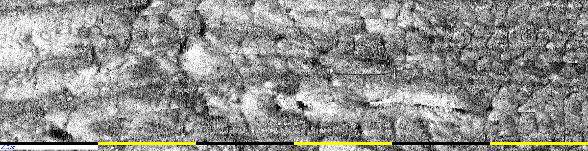
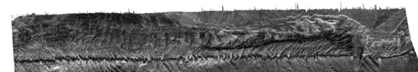
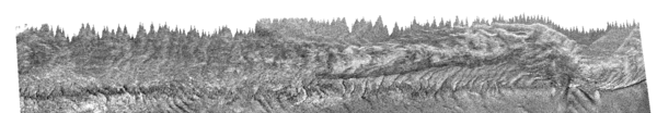
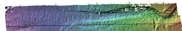
Submerged Tree:
In ~ 4m of water, there was a ~30m long displaced tree that was
aligned with the flow with the branches all downstream. At high
tide, the entire tree was just submerged. As we hadn't had the
chance to observe the delta top at low tide, we hadn't checked for
these common displaced debris (as we usually do). As a
result, we steamed over it unknowingly Fortunately, however, the
highest branches, at high tide, were still ~ 1m below the
transducers. And we happened to run right over and along the main
trunk of the tree. It was thus nicely imaged by both the EM2040P and
EM710, although from slightly differing aspects (as they are
separated by ~ 2m across the vessel and ~ 4m along the vessel). The
following images demonstrate the appearance of the tree and all its
branches.
2040 bathy.
|
710 bathy
|
2040 backscatter
|
710 backscatter
|
2040 animation showing the individual branches
|
710 animation showing the individual branches
|
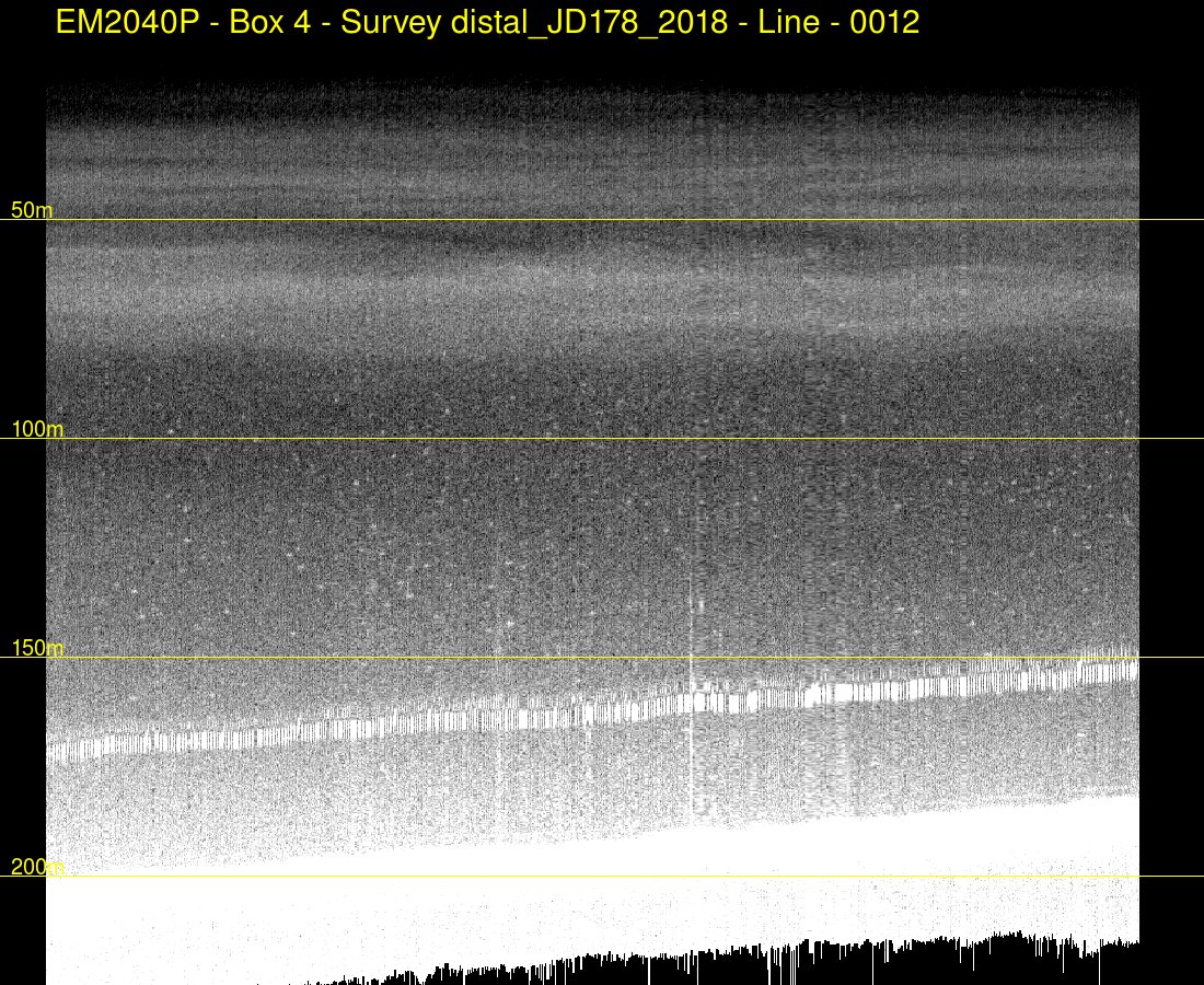
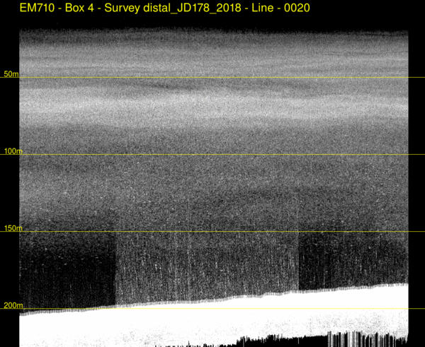
Depth performance in
100m +.
Race Rocks provided a maximum depth of 100m in high backscatter
sands and gravels. The upper Howe Sound Basin, however,
provides an opportunity to asses the EM2040P in depths to ~ 230m in
significantly lower backscatter muds and muddy sands. The area is
well known from extensive EM710 surveying with the CSL Heron.
The following example shows a transect, running from 100m to
170m. As can be seen, the EM710 is holding a constant swath
width (it is actually constrained to 250m across track). In
contrast, the EM2040P is having to pull in as it is attenuation
limited.
For the bathy that is acquired, the two systems are almost
equivalent in these depths. The backscatter imagery pattern is
basically the same - the 2040P claims a higher absolute backscatter
strength (if we are to believe its calibration - and assuming we
used the right attenuation coefficient). For these sediment types,
there is no immediately obvious frequency dependence in the pattern
(although we haven't looked at this hard yet).
EM710
|
EM2040P
|
|
|
|

|

note visibility of bottom hugging scattering layer in centre
of image.
|
note -less/not obvious bottom hugging layer. And the
bottom following echo
which is the 710 multiple overprint (as synchronized).
|
Water
Column Imaging Performance - Zooplankton/Suspended Sediments:
As part of the Squamish experiments, there is a long history of
using the EM710 water column to detect near seabed and mid-water
intrusions related to off-delta hyperpycnal flows. At short
ranges, where the M3 at 500 kHz is usable, it has always been clear
that the shorter acoustic wavelength responds better to suspended
sediment and less to the zooplankton layers and bubble plumes in the
fjords.
Thus this segment compares the 300 kHz water column imagery from the
2040P with the 70-100 kHz data from the EM710.
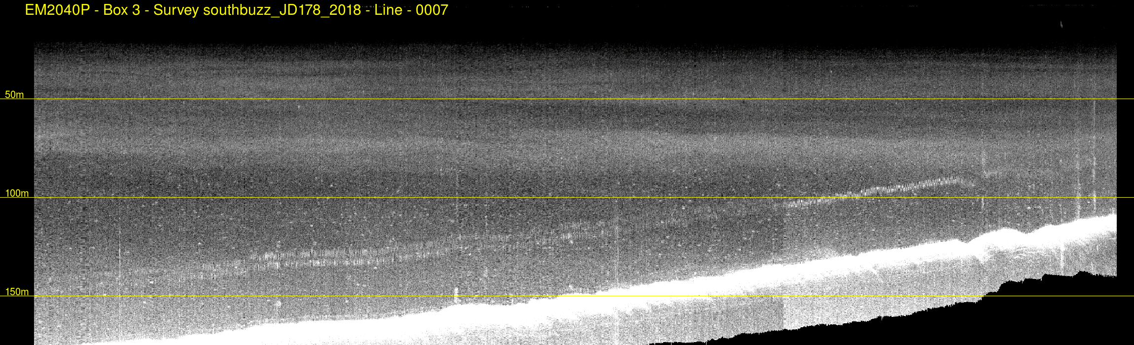
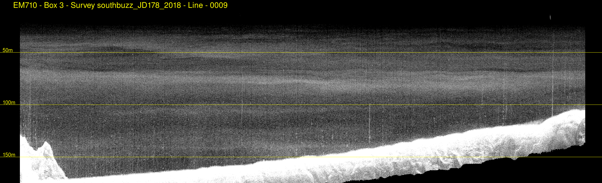
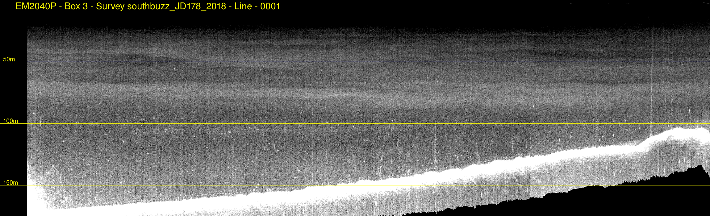
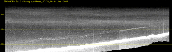
deep (~200m) performance:
The example below is from the distal part of the prodelta (180-200m
depth). In this case the Heron was transiting between two
points and in the middle of the transit it opened up the engine
revs. As can be seen, the 710 shows this clearly, but the 2040 is
less affected. This may, however, in part be because there is
already so much noise in the 2040 due mainly to attenuation.
EM2040P
note synchronized - hence bottom following multiple
|
EM710
note when prop speed is increased and then decreased.
|

note -bottom following 710 multiple as synchronized
|
note central period when the engine RPM was increased
|

note the swath is clearly attenuation limited (can't achieve
+/-60deg),
varying as the bottom backscatter strength varies
|
In contrast the 710 is getting its full swath width
-actually limited by the operator setting +/-300m (left) or
+/-200m (right).
|
2040 BS (note less dynamic range)
|
710 BS - note that the 2040 pulls in whenever the seabed BS
drops.
|
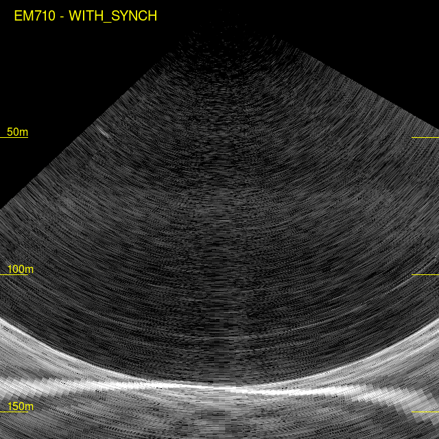
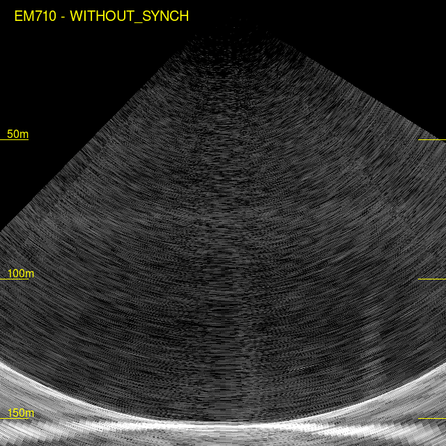
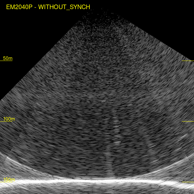
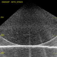
Synchronization Issues:
As shown above, if these sonars are synchronized, then the strength
of the near-nadir multiple from the EM710 is sufficient such that it
shows up at a constant - off- seabed - echo in the EM2040
imagery. The two images below illustrate the effect, with and
without synchronization.
With synchronization, the bottom mimicking echo from the 710 ping
from the previous swath is clearly visible. Without synchronization
it goes ,away but we clearly see the interference in the across
track displays.
EM710
|
EM2040
|
with sync
|
with sync
|
no sync
|

no sync
|
710 with sync
|
710 without sync |
|
2040 with sync |
2040 without sync
|
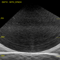
no sign of the 2040
usual - imbalance
- 1st v. 2nd swath
|
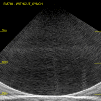
still no sign of the 2040
|
<<<<
>>>>
|
note- bottom-tracking
precursor (710 multiple)
|

note - rare but
present interference.
|
Future
Plans - 2019 and beyond
The 2018 deployment was the first time that a 2040P had been used by
the Heron. As such it required significant effort to install and
calibrate and (most importantly) support the kmall format and get
familiar with SIS-5. Should there be the opportunity to borrow one
again, I think there is still much more to learn.....
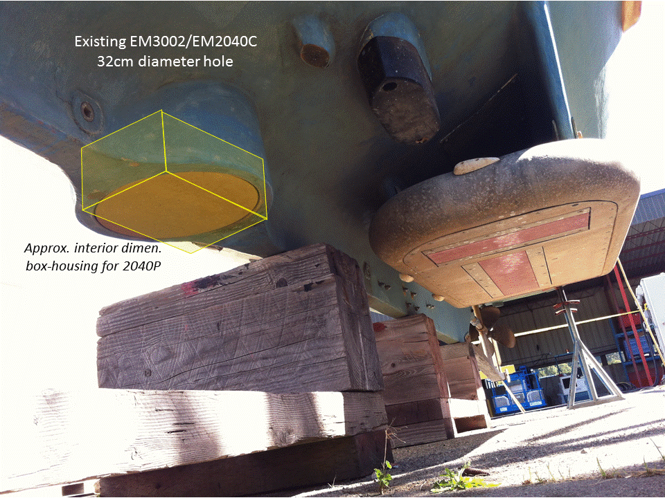
If a more permanent loan were possible, we would consider modifying
the flush keel EM3002/EM2040C blister so that the 2040P system could
be used more freely and at higher speeds.
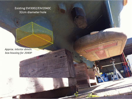
|
 |
underside of Heron - showing
existing tapered keel-pod
for the EM3002 or EM2040C - which could be reshaped for a
2040P
|
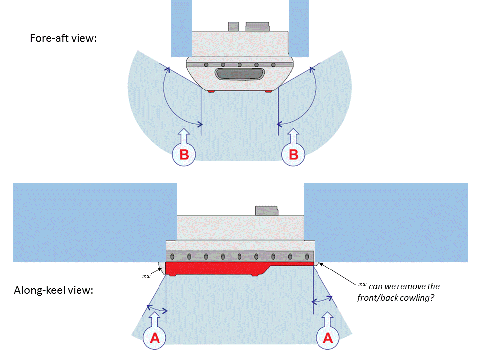
Thoughts on how to semi-flush
mount a 2040P.
Problem being, of course, how to handle the height
difference of the Tx and Rx.
|
Things we didn't get around to:
- repeating the multi-spectral surfaces at 200, and 400 kHz.
- the standard vertical accuracy testing
- the extinction testing (Haro Strait - 370m gravels and Georgia
Basin - 420m muds)
- the concrete cubes at Warrior Point (preferably before
the summer thermocline develops).
- monitoring the Cordova sand waves over a spring tidal
cycle (with ADCP and MVP running).
- capturing the Race Rocks internal waves during full
spring tides.
- the Steveston Channel salt wedge.
- try out the new wider swath options.
- calculate the beam pattern residuals for all modes.
- getting the synchronization right.
And other tests we'd like to perform:
- assuming we get the Brazilian REMUS-100+GeoSwath there
(hopefully summer 2019) - do a direct comparison at different
flying heights.
- if we can borrow an EK-80 - perform the Lurton tilted EK v. EM
absolute calibration.
page developed onboard and in
October/November 2018 by JEHC