![[IC Logo]](Images/banner150.jpeg)
![]()
" SynSwath is an useful tool,
illustrative, playfull, cool."
Introduction
Keyboard shortcuts
Tool Boxes
OMG/UNB Syn-Swath
Widget Application Launcher
Useful command lines
Boundlessly
References
Introduction
SynSwath is a synthetic swath sonar simulation package for training and applications developed by John E. Hughes Clarke, leader of Ocean Mapping Group at the University of New Brunswick. In-house 3-D graphical teaching tool was developed on Silicon Graphics workstation using openGL graphic libraries. It allows the user to visualise all the geometric relationships between acoustically steered line arrays on a dynamic hull (i.e. rolling, pitching, heaving and yawing).
This document contains examples of SynSwath images, description and explanation of keyboard shortcuts and other useful operational steps. Firstly, you need to find the file SynSwath_WORKS* (directory code/gl/demos/). SynSwath Tool Box and Display Window appear after writting SynSwath on the command line. Do these snapshots seem familiar? Remember illustrations from GGE 3353?
Notice: SynSwath crashes after hitting
!
Keyboard shortcuts
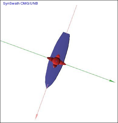
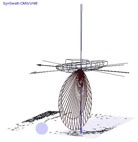
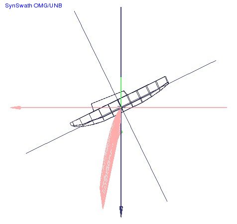
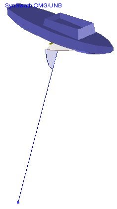
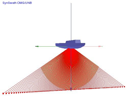
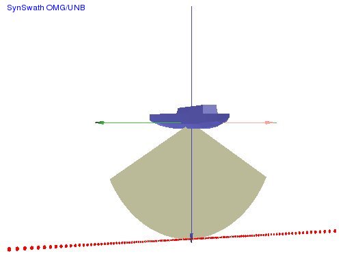
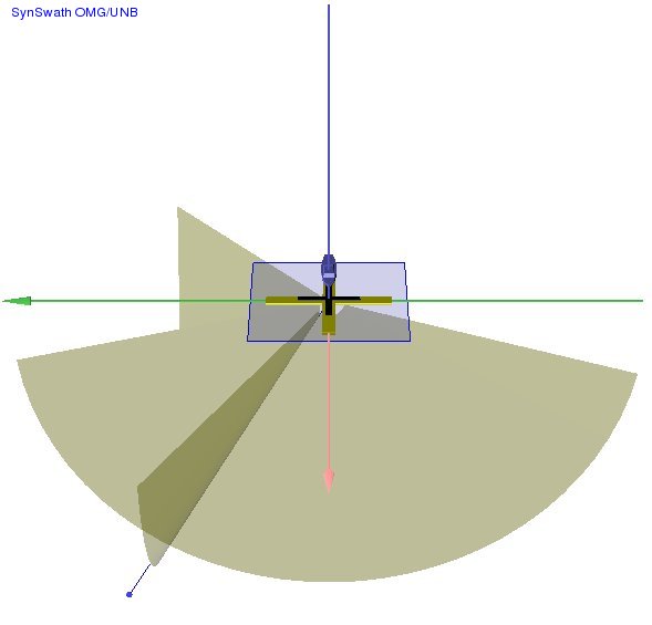
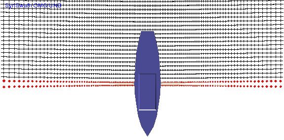
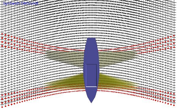
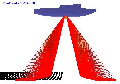
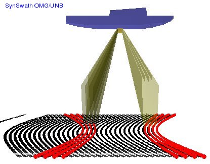
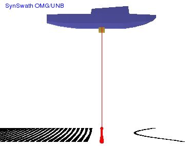
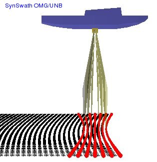
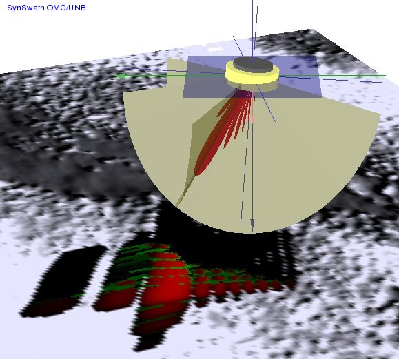
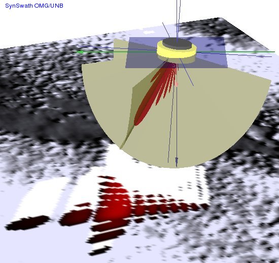
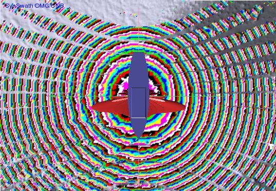
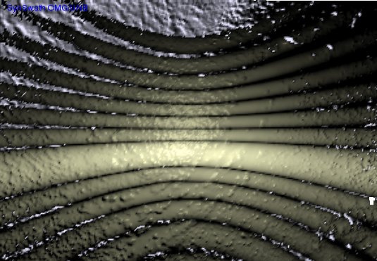
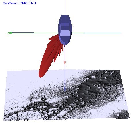
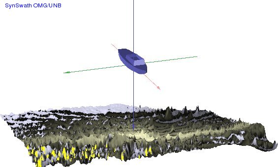
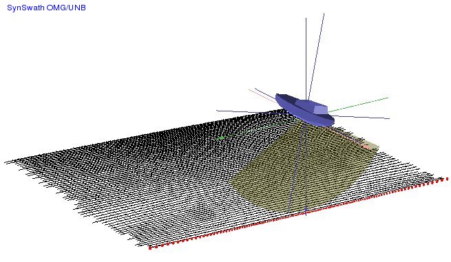
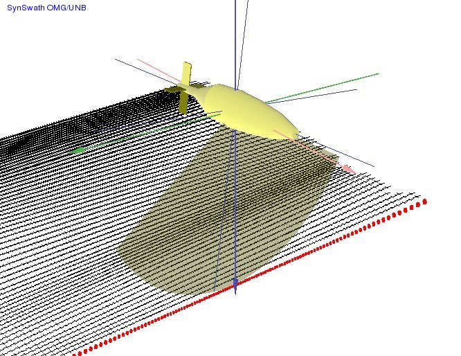
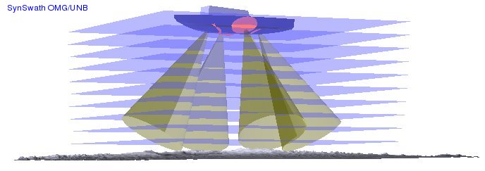
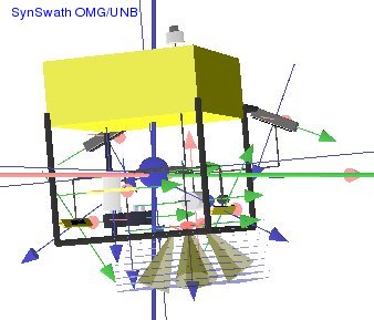
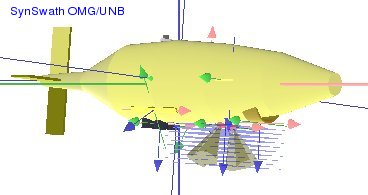
Since SynSwath has a few unresolved bugs you may find some useful shortcuts. For example, the A key toggles the axes and transmitting beams with T (see Figure 1). Receiving beams can be displayed with R (see Figure 2); more shortcuts follow in the table bellow:
Keys are window sensitive !
Shortcut
Meaning A display 3D axes ←
→rotate image about Z-axis ↑↓ rotate image up and down
+- zoom in / out T toggle transmitter beams
R toggle receiver beams
B toggle display product of T and R
Y toggle beam pattern
E toggle blue eye 
(wire render, plate, axes)
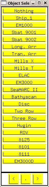
W toggle water state Figure 1: Transmitter, Axes. S object selection (nothing/ ship1/ EM 1000/ SBat 9001/ SBat 9002/ longitudinal array /transversal array/ mills “X”/ mills “T”/ ELAC/
EM3000/SeaMARC II/ Bathyscan/ Disc/ Two row/ Three row/ Hugin/
ROV/ 8125/ 8101/ 8111/ EM3000D)G
rolling, pitching animation
note: faster with wire render (Z)

Z toggle wire render / full render C cone steering, B displays both cones (! do not steer so that they do not
intersect - it crashes the program !)M dumped scene X toggle rays
V toggle recording (.ppm files) 0 change axis colour 9 front view (green axis) 8 sideview (pink axis) 6 adds a little sonar to the object drawing () 7 top view
1, 2 lighter / darker properties of object surfaces
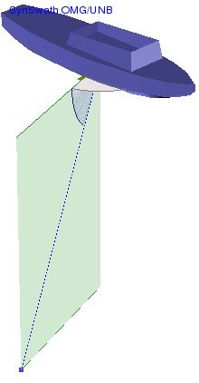
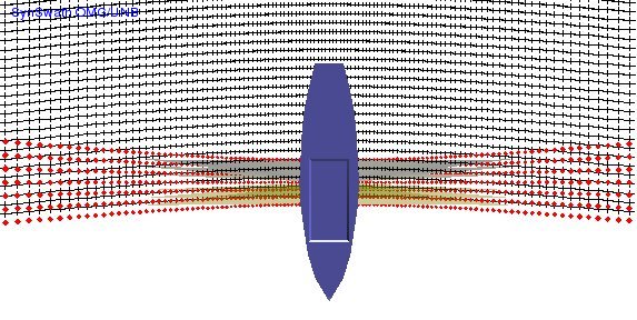
Figure 2: Receiver, Axes, Cones, Water, BeamVect. 5
middle looking
P toggle plate (if there is some!) I
toggle acoustic illumination of plate
Q quit the program (! SynSwath crashes after hitting Tool Boxes
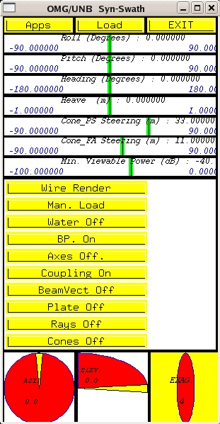
OMG/UNB SynSwath Tool Box
Basic SynSwath window is SynSwath Tool Box. By hitting "Apps", you get Widget Application Launcher.
!SynSwath crashes after clicking on "Load", "Man. Load" and "Wire Render"! Other icons have the same meaning as keyboard shortcuts described above.
SynSwath Tool Box Icons:
Wire Render Render / Full

! Window button usually crashes the program. Instead of the button click use shortcut Z !Man. Load would load a manually generated beampattern file !BUT if doesn't exist, crashes program ! Water water level BP both transmitter and receiver beams roll or do not roll with the ship Axes displaying of 3D axes Coupling Coupling On - beams move with ship / Coupling Off
- beam does not follow the ships movement (roll 17º, pitch 25º, power 18 dB).
BeamVect 1 click: shows one beam vector; 2 hits:
shows azimuth and depression angle; 3 hits:
displays a plane with refraction solutions.
+ and - keys (in beamvect button box) will plot a refracted ray bending either up or down.
Plate Works if plate is imported (knowhow see bellow). Rays Toggle Rays On / Rays Off
Cones steering cones
Widget Application Launcher
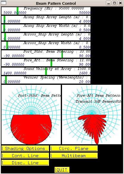
Widget Application Launcher offers various menues (e.g.beam patern) and submenues (e.g.Shading Options). Widget Application Launcher
has the following menu:
beam pattern
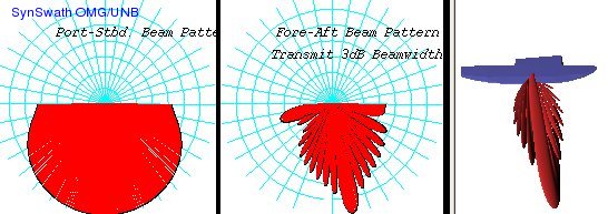
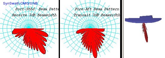
model the beam pattern with help of polar plots (maximum response axes): transmitting , receiving
, product of both
(frequency 95kHz, PS beam steering 33º, FA beam steering 11º); interactive changes of frequency; along and across arrays; beam steering parameters, to use vernier spacing Illuminated Plate and Bottom Detection Window must be open.
The longer array length, the narrower beam. Fully functionality was never brought up (across arrays, sound speed).
Shading Opts leftover from previous 2D versions of this tool, does not work in this version
Circ. Plane circular plane, single beam echosounder (slow change arrow length)
Cont. Line continuous line Disc. Line discontinuous line, proper steering
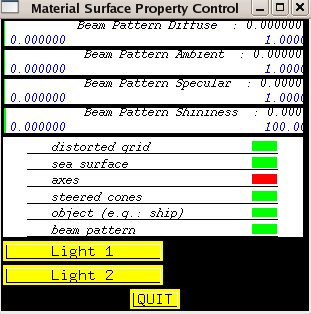
Multibeam multibeam pattern mat.props.
material surface property from OpenGL (beam pattern, cones: diffuse, ambient, specular, shiny)
note: does not work with plate (seabed is illuminated acoustically)Light 1 instead of this button, use key 1
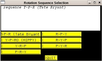
Light 2 instead of this button, use key 2 Rot.Seq.
rotation sequence selection; "Do you pitch around original axis or around axis of actual ship?"
YPR
Tate BryantYaw, Pitch, Roll, this order is an official order used by ships and all world airplanes; roll around the axis which was heading and pitch changed
YPRo HIPPY Yaw, Pitch, Roll; roll around unpitched axis (Hanewell)
YRP Yaw, Roll, Pitch
PRY Pitch, Roll, Yaw
RPY Roll, Pitch, Yaw
RYP Roll, Yaw, Pitch
PYR Pitch, Yaw, Roll
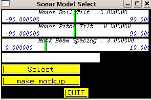
sonar model
sonar model select (mount roll and pitch tilt, mock beam spacing)
This assumes on the command line you have listed "-bf xxx -bf yyyyy -bf zzzz " etc... This means you are pre-loading a "beam footprint" model. Example exist for various common sonars - they specify EA or EDBS beam spacing, beam size, spacing and ping sequence.
Select beam footprint model selector
make mockup It allows you to make a crude beam model using the slider bars. This actually implements it.
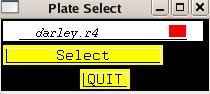
plt.sel.
select imported plate
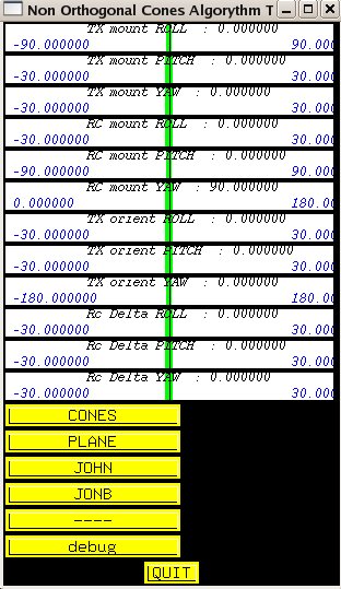
cone in cone
tests non orthogonal cone alghorithms (! do not steer so that they do not intersect - it crashes the program !);
translations and rotations: TX and RC roll, pitch and yaw, TX orientations and RC deltas in RPY directions
CONES
display cones
PLANE display horizontal plane of transducer
JOHN This is historic - these are two versions of code to implement the rotations and calculating the final beam vector.
JONB this one does NOT exactly match the intersection of the two cones - i.e. not conforming to openGl math.
---- nothing
debug nothing
currents
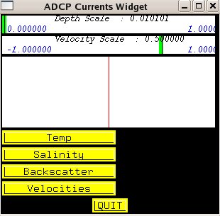
ADCP currents widget
An only partly finished widget - have to load a vertical profile of current vectors using the "-currents" command line option. It reads it a sequence of ADCP vertical velocity profiles and you can then make an animation showing the ADCP current field evolving over time.
Temp - not implemented
Salinity - not implemented
Backscatter - not implemented
Velocities - not implemented
LBL
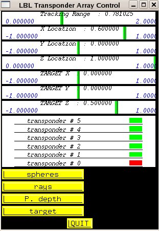
Long Baseline Transponder Array Control
A widget to display LBL geometry can change the location (and presence) of each one of the LBL transponders as well as the location and depth of the target. Then ranges from each target are calculated and the intersection of each sphere is displayed.
SLIDER BARS ---
target x-y-z is movable
click on the list of each transponder to select - then use X-Y-Z slider bar to move.
space bar on each transponder turns it on and off.
spheres toggle spheres
rays toggle rays to the target
P.depth This shows how a pressure gauge on the tracked hydrophone will solve for the depth - often LBL geometry is so flat it reduces to a 2D solution and you can't solve for the vertical very well.
target toggle target
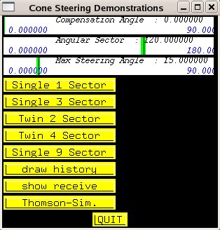
cone steer
cone steering demonstrations
This widget shows how active motion stabilisation is implemented.
! Have to use an ASCII motion time series ! >synSwath -ts gggggg
get one from here: ggggg
SLIDER BARS ---
Compensation angle , when pitch stabilising is the elevation angle when the pitch stabilisation is perfect. Default is at Zero, ie. all other beams are OVER pitch compensated. Bellow 35-40° the nadir will be under compensated, 35-40° perfect, and > 35-40° is over compensated.
Max Steering Angle - for yaw or pitch stabilsation. This is the max steering that will be implelented on the transmitter. For demo purposes it is good to increase this form the default 15 to ~ 70°.
Angular Sector - starts off as a 120° sector (+/- 60°). User can change it to whatever she/he likes.
Also need to have the Animation widget up where you choose to turn on/off Yaw/Pitch/Roll stabilisation.
Single 1 Sector Default - only 1 transmit sector with only one steering angle allowed.
Single 3 Sector e.g. shallow EM300 / EM120 or EM710
Twin 2 Sector e.g. Hydrosweep MD
Twin 4 Sector what Fansweep could do BUT IT DOESN'T
Single 9 Sector e.g. deep EM300/EM120 (used in Labrador Sea)
draw history together with Go icon in Animation window
Thomson - Sim Cycles through - Single swath - Thomson SeaFalcon (7 swaths shown but only really 5) - then 2 swath EM710 and finally 8 sectors of the new Fansweep 30. 
/


/

/


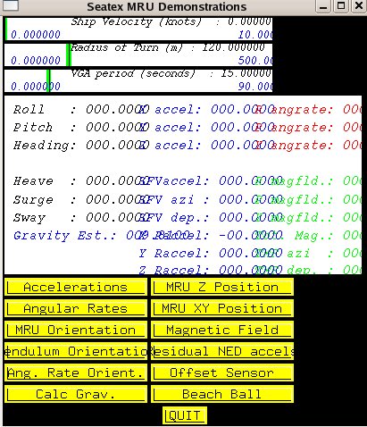
MRU demo
Seatex MRU-6 (serial port connection) sensor outputs to the computer screen. Objects
object selection menu (the same as keyboard S). Hitting the point in the middle will return object to default size. Hold left mouse button to roll, pitch etc. the object and to move green axis. Plate
rotate, roll, pitch, expand, vertically exaggerate (sun illuminate with +- buttons), middle mouse click, arrows buttons
when you are on the window with mouse, + - keys serve as a vertical distance from the ship
Phase
phase transmit - receive product 
Int.
intensity transmit - receive product 
Time
!!WRONG!! !!WRONG!! Time Off ! works just together with Bottom Detection Window !

Centre
Edge
Select
default closes Plate Window + / - bt.
bottom type; first minus / second minus
/ plus

+ / - sun
sun intensity
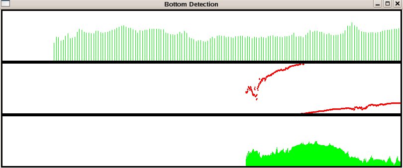
Bot.Det.
interactive bottom detection window ; horizontal axis is TIME; lowest part in green displays INTENSITY (time of bottom detection) with BINS in vertical axis (up and down arrows for scaling); middle part in red is PHASE with vertical axis 0 - 360º; upper part of window serves as a display of ZOOMed intensity) which works only after Illumination, or with GO button in Animation menu, note: assumption is an imported plate (see bellow)
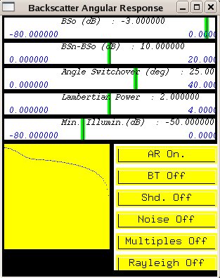
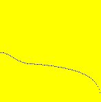
Ang.Resp.
if you keep mouse arrow on the "Noise On", you can increase or decrease noise amount with up and down arrow keys corrected for spherical spreading
AR
Angular Response; AR Off is radiated intensity (much smoother!), no graph in AR Window;
-50 dB/ -80 dB
BT
Shd.
shading turns yellow when unimagable
Noise
Noise On / Noise Off
Multiples
Rayleigh
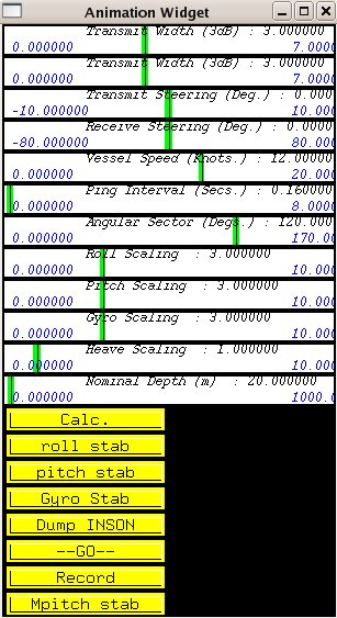
Animation
time series of roll, pitch, heave, heading and time; faster when beam pattern off; !do not animate with plate!
calc.
roll stab unstabilized and stabilized
roll
pitch stab unstabilized pitch ; mechanically better than electronically
Gyro stab stabilize Gyroscop
Dump INSON
--GO-- START button for recording; number of samples saved
Record automatic recording of .ppm images in intervals of seconds Mpitch stab stabilize pitch movement if there is some waving
ADCP
Acoustic Doppler Current Profiler
A widget to explain the workings of an ADCP - not entirely finished.
beam patterns
display beams of ADCP transducer 
beam vectors
currents
adds paralell current layers to the water column
bottom mask
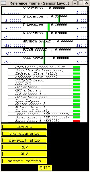
Ref. Frame
display reference frame of used object; keyboard shortcut: SPACEBAR
note: After klicking sensor play with its layout (pressure gauge, subbotom profiler, sidescan, GPS anntenna).
levers
Levers On / Levers Off
transparency
Transparency On / Transparency Off
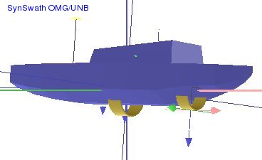
default ship
display ship
ROV
display ROV
AUV
display AUV
sensor coords
display sensor coordinates Useful command lines
How to import your plate?
>synSwath -plate darley
this command requires darley.r4, darley.sun and darley.BT* (renamed extention of 8bit file) files where darley is name prefix
>synSwath -ts mont_211_24.merged.ascii -level 1.0 -plate darley
How to take a screenshot?
>import example.jpeg
How to resize an image?
>convert -resize 200 example.jpeg example_smaller.jpeg
How to label an image?
>convert -font helvetica -fill blue -draw "text 10,15 'SynSwath OMG/UNB'" example.jpeg example_labeled.jpeg
>xv example_smaller.jpeg
Screen resolution of 3D window can be changed to 600 times 600 pixels with:
>synSwath -winsize 600 600
Boundlessly
The sonar parameters, including beam width, beam steering, side lobe suppression are mathematically modelled and the resulting 3D beam pattern can be projected onto a convenient regular terrain model to illustrate ensonification patterns. The bottom detection time series can be derived from that illumination pattern and noise added to simulate the bottom detection process.
References
SynSwath - a synthetic swath sonar simulation package for training and research applications
http://www.omg.unb.ca/SYNSWATH/OMG_UNB_SynSwath_top.html
In the time I wrote this manual JHC was still looking for proper model of ship for SynSwath main window. Do not hesitate to bring him some!
keta512@yahoo.com


