| Acoustic Imaging
of Salmonid Mariculture Sites John E. Hughes Clarke1 David Wildish2 and Anya Duxfield1 |
 |
| Acoustic Imaging
of Salmonid Mariculture Sites John E. Hughes Clarke1 David Wildish2 and Anya Duxfield1 |
|
| (1)
Ocean Mapping Group Dept. Geodesy and Geomatics Engineering University of New Brunswick, CANADA |
(2) St.
Andrews Biological Station Department of Fisheries and Oceans St. Andrews, New Brunswick, CANADA |
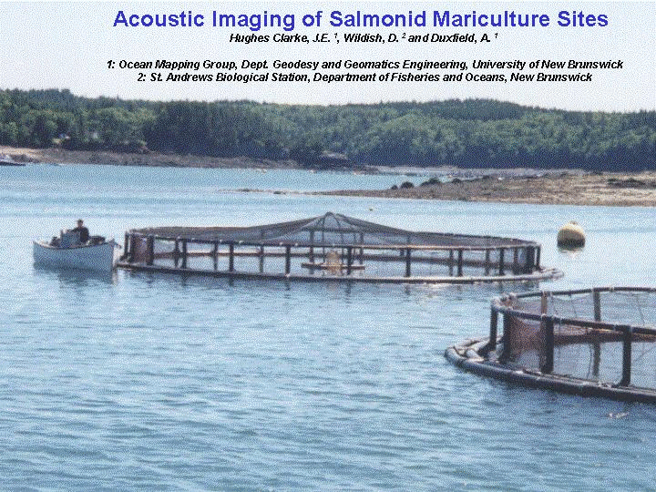 |
Since 2000, the Ocean
Mapping Group (OMG) has become involved in acoustic imaging of Salmon
Aquaculture sites in the Fundy Isles region. The interest was
originally driven by David Wildish and coworkers at the St. Andrews
Biological Station (DFO), based in Passamaquoddy Bay. The images shown here are derived from a presentation made at the Canadian Hydrographic Conference in Toronto in 2002 (Hughes Clarke et al., 2002). |
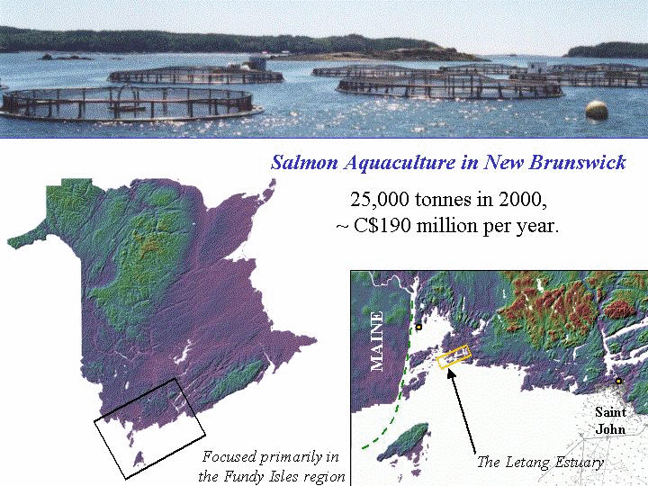 |
Aquaculture is obviously a major
industry in Southern New Brunswick. Salmon farming is focused in the
protected bays of the macrotidal region along the Charlotte county
coast. We have been involved in surveys in the region at:
In addition, over on the Gulf coast of New Brunswick, where aquaculture is focused more on mussels and oysters, we have also been involved in acoustic surveys of those sites in Shippagan Bay. |
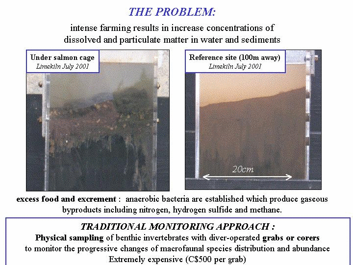 |
One of the major concerns for aquaculture in the local environment, is that the effluent, both dissolved in the water column, and sedimented on the seafloor might be harmful. These acoustic studies have focussed on the "near field" (i.e. in the vicinity of the cages) where deposits of excess feed and excrement have built up. When sampled, this material is very obvious and has a locally severely detrimental effect on the benthic biota. The long term significance of the impact of the excess feed and excrement is less clear. Earlier acoustic studies in Bay d'Espoir, Newfoundland, suggested that the acoustic signature of the excess food dissapears within a matter on months (Tlusty et al., 2000). |
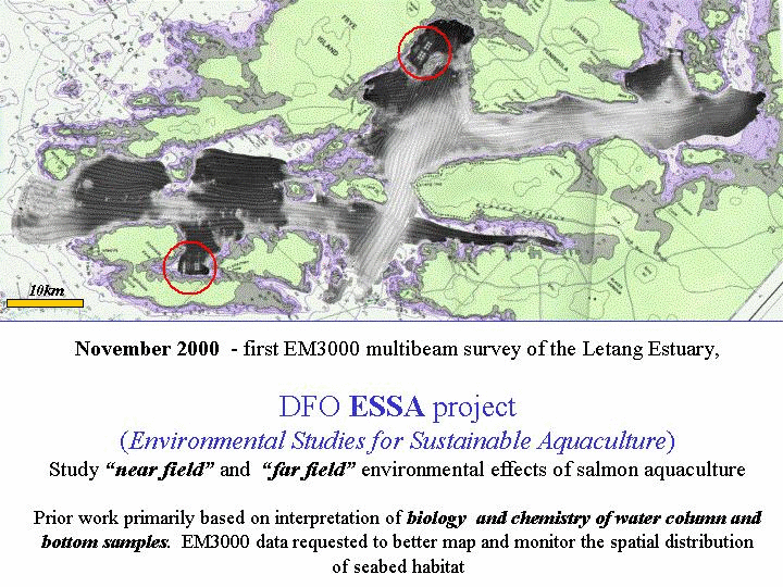 |
The initial studies in 2000 involved a CHS EM3000S 300kHz multibeam survey of the entire subtidal area of the Letang Estuary. In this area a number of aquacultire sites were directly imaged, including both the surrounds and the sub cage sediment. The OMG processed both the bathymetry and the backscatter imagery for the St. Andrews Biological Station. The sites examined included a wide range of current and seabed conditions, allowing us to examine the build up and fate of the excess organic material in a variety of current and seabed environments. |
 |
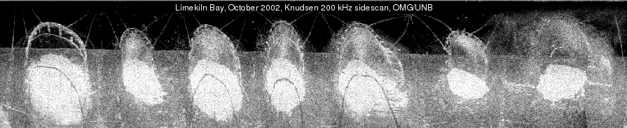
Limekiln Bay contained the most obvious signature of all the sites. In this area, one clearly sees both a bathymetric (~15cm) anomaly as well as a pronounced backscatter anomaly. The anomalies lies directly and symmetrically under the cage sites. Notably, because the EM3000 multibeam sonar hardware is mounted completely flush to the hull we are able to freely operate within and around the mooring cage infrastructure without gear of hookup. |
 |
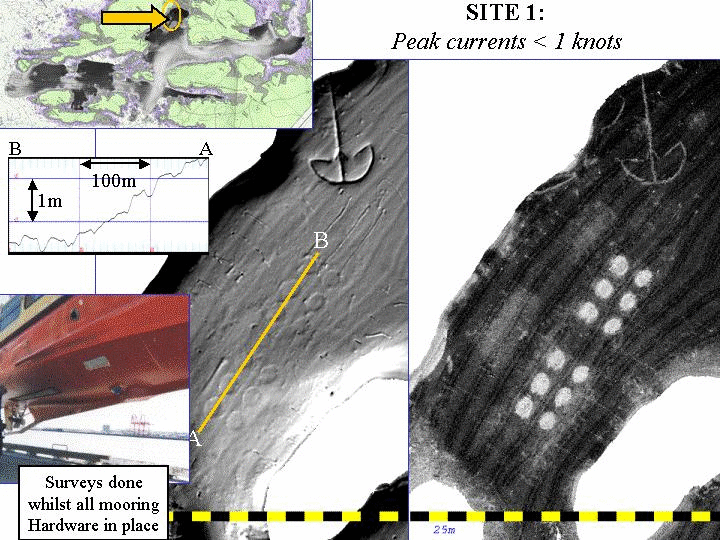
Limekiln Bay is almost totally
protected from tidal currents and thus the sediments are extremely fine
grained (mud and clay).The aquaculture sites, however, are distributed
around the Letang estuary in a variety of current conditions. The following 4 images show sites with increasing mean tidal current velocities. In this image (currents < 2knots, but significant), one sees a slightly higher regional bottom backscatter strength than Limekiln, but the signature (both in backscatter and bathymetry) of the deposits is still clear. |
 |
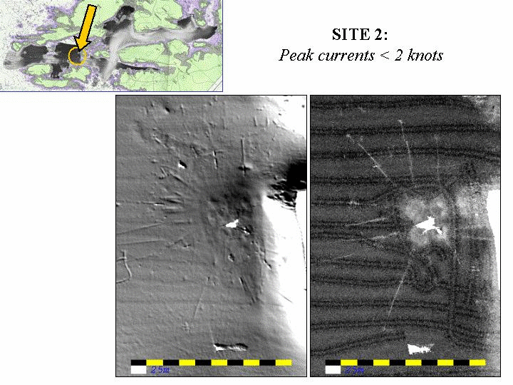
In this image (currents 2-3 knots), one can no longer see a clear signature of the sub-site deposits. It is not clear whether this is because there is no sediment (currents perhaps prevent local resuspension) or there is no contrast with the surrounding sediments. Bathymetrically one can see the physical alteration of the sediment resulting from dragging the cage mooring hardware. This indicates that the sediment is still reasonably soft (sand). |
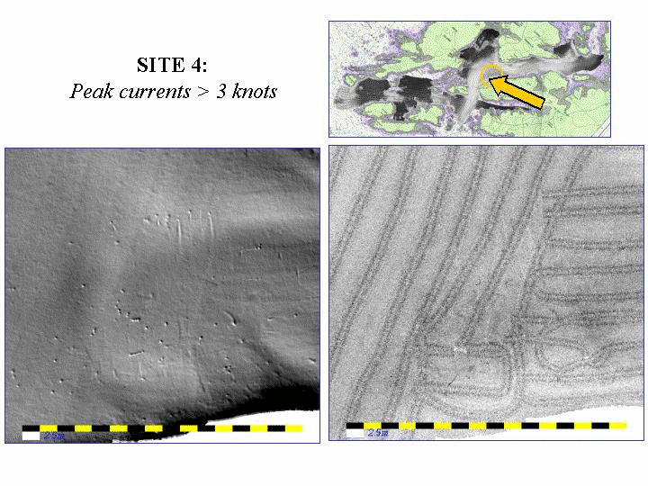 |
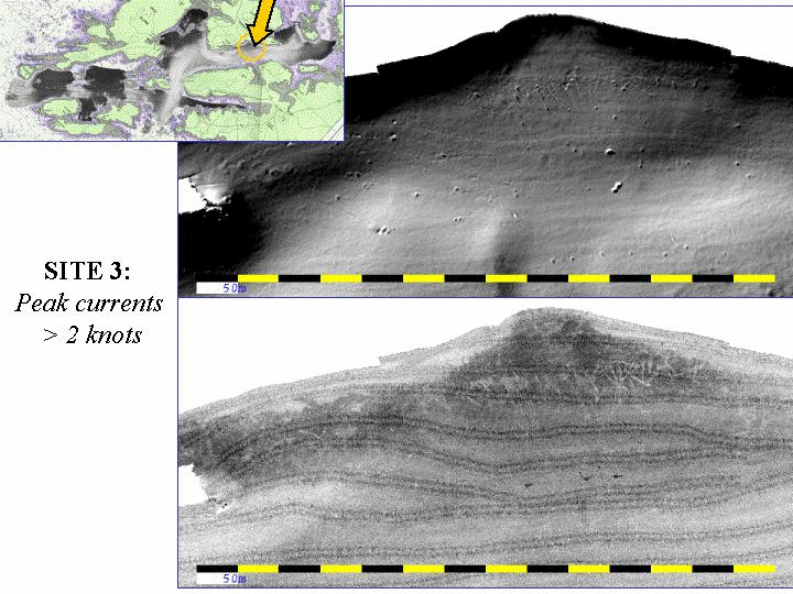
In this image, the currents are
as strong as the mooring hardware can cope with. There is no
record of the sub-site deposits (which, if present, would show up as a
lower backscatter than the surrounding sediments). And bathymetrically, only the positive signature of the mooring blocks is seen. Notably the seabed is not scoured at all indicating that dragging the mooring blocks does not easily alter these sediments - indicating probably that it consists of a gravel or cobble pavement. |
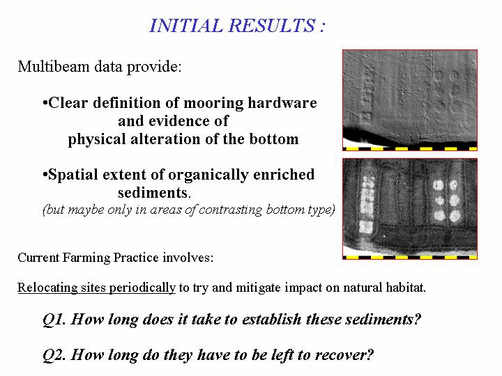 |
In conclusion then, it is clear that multibeam bathymetry and backscatter can provide useful information about the current state of sub-site deposition and physical alteration. But the next question is - how long does this deposition and alteration last? |
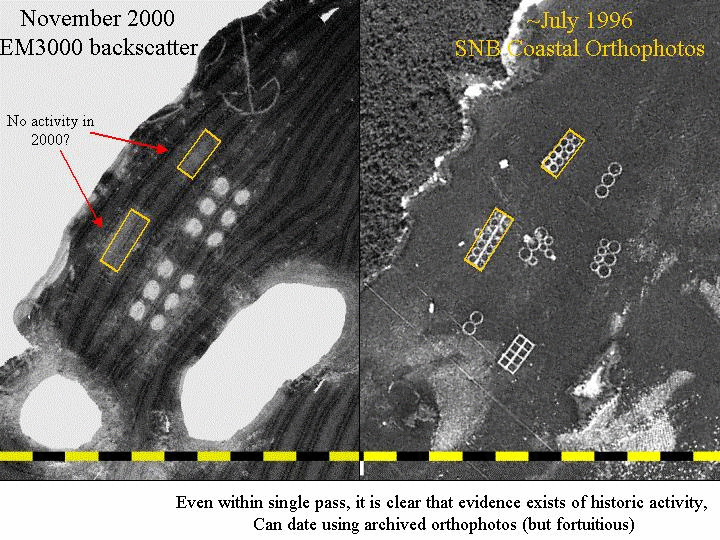 |
The following two slides show examples comparing: - 1996 aerial photos of the cage locations - 2000 bottom backscatter images of the deposits. One can see that there are relict signatures of the older cage sites. |
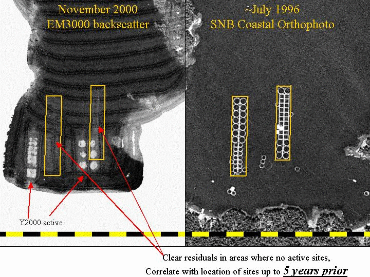 |
In this example, the relict signature is just visible indicating that within ~ 4 years the deposits fade away. Thus it would be feasible to do repeat surveys to establish this decay in more detail. |
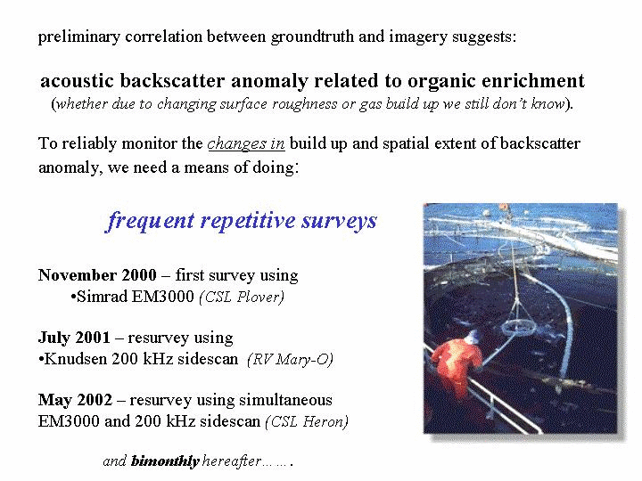 |
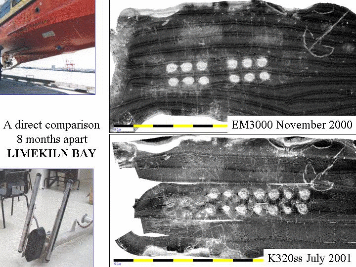
To address the question of the time scale of reworking of the sub-site deposits, we conducted three surveys of the Limekiln bay site over 2 years. We also tested out the use of keel-mounted sidescans as an alternative to using the more expensive multibeams. |
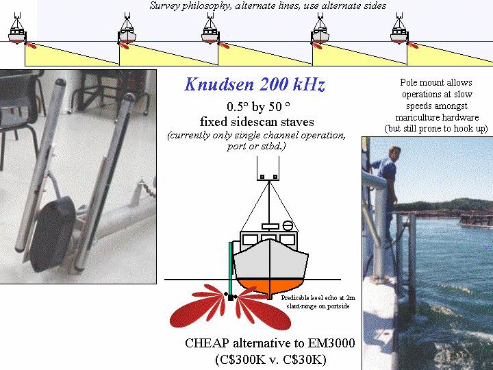 |
Recognising that multibeam
survey systems are usually prohibitively
expensive and require extensive operator training, we were
interested in using a cheaper technology that might produce
near-equivalent results. As part of trials for the CHS, we had
been experimenting with pole or keel-mounted sidescan staves for
imaging shallow (< 15m) seabeds as an alternate and more
cost-effective approach to inshore survey. More details of the
development of this method can be found on another
web page. In 2001 we had implemented this technology on a pole attached to the RV Mary-O, allowing single sided (but switchable) imaging capability. We deployed this technology in July 2001 to reimage the Lime-Kiln Bay sites. |
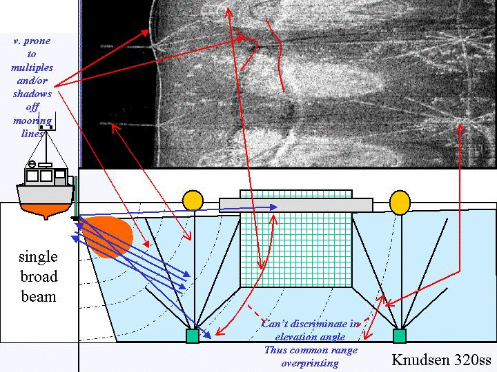 |
Whilst it was immediately clear
that the sidescan imagery was seeing a very similar backscatter image
to the multibeam, there were important differences in imaging geometry
and the handling of the elevation angle issue. For the sidescan method, there is no discrimination in elevation angle and thus all features within the transmit plane that lie at a common slant range are overprinted. Because the aquaculture hardware is suspended in the water column above the seabed detritus, the echoes from the hardware become irretrievably overprinted onto the seabed backscattered returns. As a result we see both the echoes from the water column hardware and the shadows cast by that hardware on the seafloor imagery. |
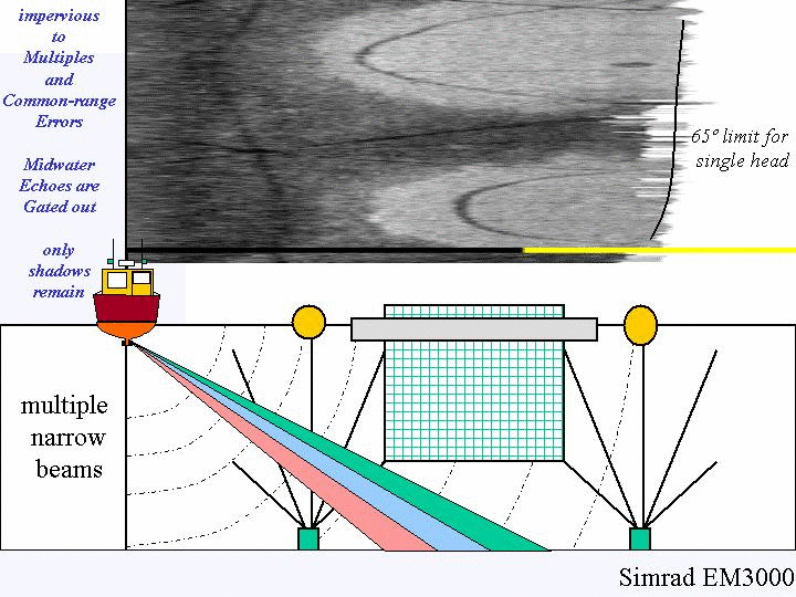 |
In contrast to the sidescan
geometry, the multibeam method has discrimination in elevation angle
to within sectors, of the width of the receive beams (1.5 degress
growing
slighly with steering). Thus echoes at the same slant range, but at
different elevation angles are not confused and thus a more faithful
representation of the seabed is preserved.. Neverthless, the shadowing cannot be avoided (the beams, even in a narrow elevation angle, still have to look at seafloors in the "lee" of the shadow cast by water column targets.). Thus shadows are visible, but can usually be identified unambiguously as the underlying seafloor is never rough enough to cast its own shadows. |
 |
Nevertheless, despite the
differences in imaging geometry between the two methods, both still
are capable of mapping out the gross spatial distribution of the
seabed backscatter anomaly due to the excess food and excrement
beneath the cages. Qualitatively comparing the 2000 and 2001 images, we clearly see that the original cage sites active in 2000, have been abandoned and the current cages lines are offset. |
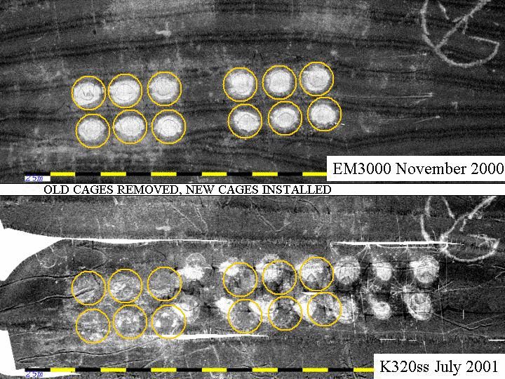 |
Looking in more detail at the
2001 imagery one can see that the decayed signature of the 2000 cages
is still present although attenuated and perturbed. One also clearly sees that the sidescan, because it looks out to lower graing angles, is better able to distinguish seabed ridging due to movement of the mooring blocks. These are seen in the multibeam bathymetry (as topographic anomalies) but are not in the multibeam backscatter as the grazing angles are too large to cast shadows. |
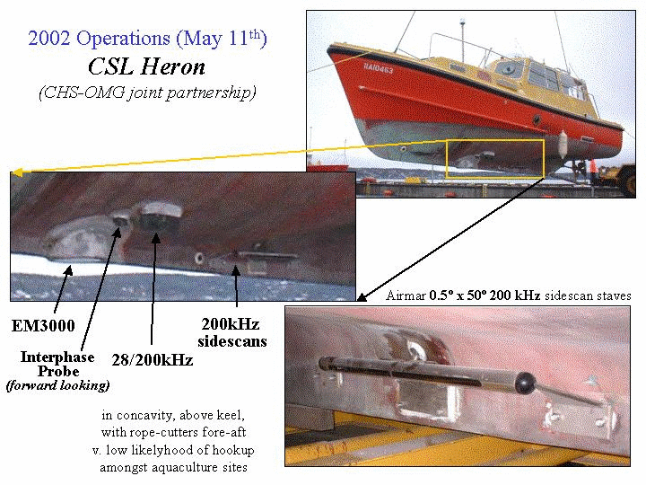 |
Over the winter of 2001-2002,
the sidescan stave pair were permanently
mounted onto the keel of the C.S.L. Heron.
Heron is now the prime inshore research vessel operated by the Ocean
Mapping Group. In an effort to streamline the sidescan mounting,
to allow higher speeds and prevent hooking the instrumentation up, they
were attached to the skeg keel of a conventional displacement
hydrographic survey launch. The mount proved successful with useful data acquired at speeds of over 11 knots (with of course corresponding loss of along track resolution though). |
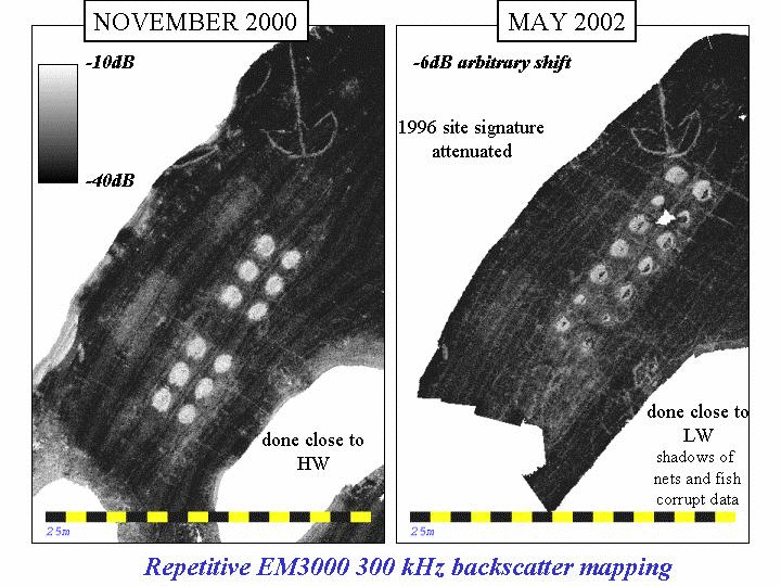 |
In May 2002, the first
deployment of C.S.L. Heron to Limekiln Bay took place. Both the EM3000
and the Knudsen keel-mounted sidescans wer deployed. This allowed us
to directly compare the relative perfomance of the two systems. One can see the change since 2000 involving a decay of the old signature and the establishment of an offset site. Note that there are cast shadows within the footprint of the new site. These shadows are from the dense mass of fish in the cages indicating that they are more mature than in 2000. |
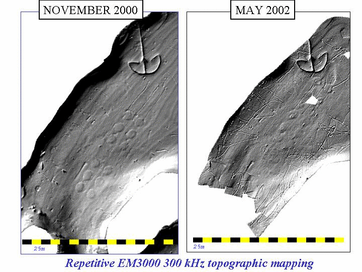 |
The topographic signature, so strong in 2000, has been lost. New signatures are establishing themselves under the new cage sites. Note that there has been extensive dragging of the mooring hardware since 2000. |
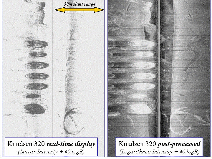 |
An exercise in enhancement. The knudsen data in 2002 was logged as linear intensity and needs logarithmic compression to bring out the details of the seabed signatures. The signature of the mooring hardware (and the dense swim bladders in the nets) are 10-20 dB stronger than the surrounding seabed echoes. |
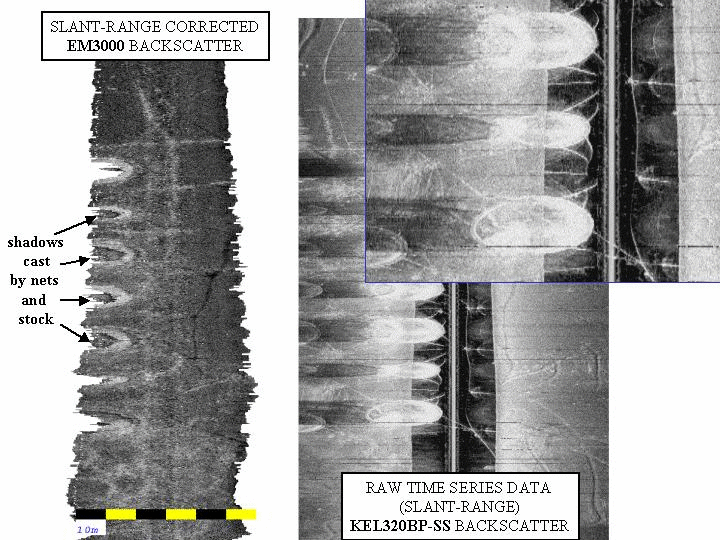 |
But now (in 2002) the fish in
the cages are larger (and or denser packed),
actually casting significant shadows, and thus, in some cases we lose
all sense of true sediment behind the fish. For the knudsen sidescan, the cage echo shows up at a shorter slant range than the seabed echo. The water-column segment of the sidescan image (that before the first seabed arrival) reveals details of the suspended mooring hardware. This echo completely overprints the seabed signature. If too close to the cage, mulitbeam backscatter shows an attenuated signal due to shadowing by fish |
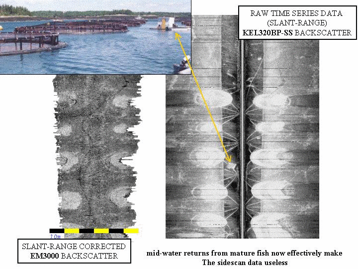 |
By being further away from cage,
the multibeam sees under it more effectively as the beams pass below
the suspended fish and nets. Sidescan shows no improvement as the
common
slant range problem remains. The sidescan image shows sea surface targets clearly imprinted (the feed hut). |
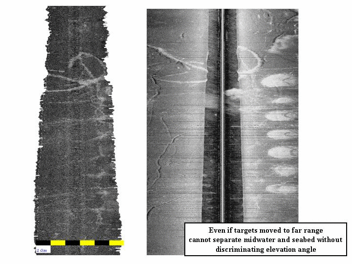 |
Even if one moves the target to
the far range of sidescan (beyond the multibeam
swath), the cage echo remains superimposed irretrivably from the
seabed echo in the sidescan data. The cage echo now looks like a seafloor target (because no shadow cast) but it is just that the two circular echos are colocated. Thus the keel-mounted sidescans only can map the seabed deposits when either the cages are removed or there are few fish in the cages. In contrast the multibeam can see under almost all the time |
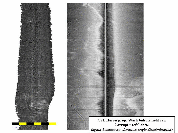 |
An operational problem for the
sidescan is that the
prop wash from the prior line takes a long time to dissapate and as the
source-receiver is near the surface, a significant part of the
radiated energy is aimed at the bubble wake of the previous line.
Functionally you cannot image back on your prior track (either wait for the bubble plume to dissapate or skip several lines so the prop wash is beyond the far range). The multibeam data is unaffected as the beams do not look out horizontally at the bubble wake. |
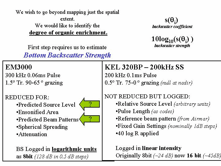 |
Whilst one can easily
distinguish the spatial extent (through contrasting acoustic
signature), a far
harder problem is to try and measure organic enrichment. Assuming there is a relationship between backscatter strength and enrichment (a huge if!), we first have to be able to provide repeatable backscatter strength estimates. This aspect - calibration - is non trivial. Relative changes (especially with identical hardware) can be usually used, but absolute measurement remains the holy grail. Source level - and beam pattern uncertainty are the biggest issues. |
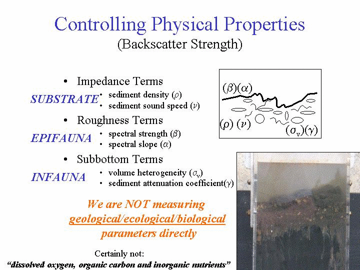 |
But that IF assumes a lot. The acoustic signature of organic enrichment is driven by a number of factors : -- the shape and compostion if the excess food pellets - contribute to roughnes and impedance - in-sediment gas bubble generation - contribute to volume scatteres and internal impedance contrasts. Separating the two would be very tricky. |
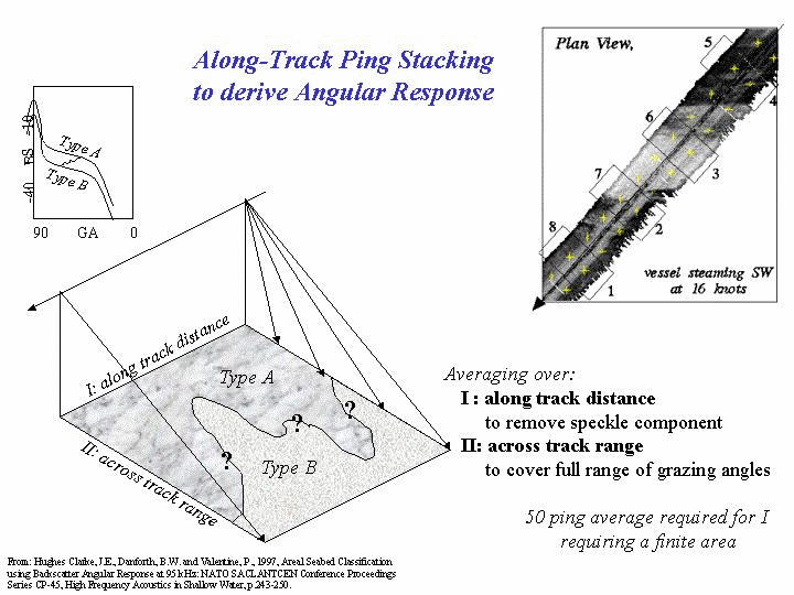 |
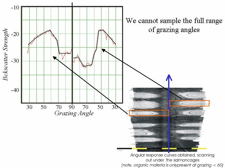
And a single backscatter
strength estimate at a
given angle can be ambiguous --- One needs grazing angle variability which requires imaging the same sediment at different grazing angles. Can't easily achieve this if the width of the patch of sediment is less than half the swath width. You tend to mix sediment types within a single swath. |
 |
Under cage sediment deposits
are, by their very nature, patchy. It is almost impossible to get a measure of the backscatter strength at normal incidence (unless the cage is removed). Thus one couldn't do vertical incidence sediment classification (like Roxanne or QTC). |
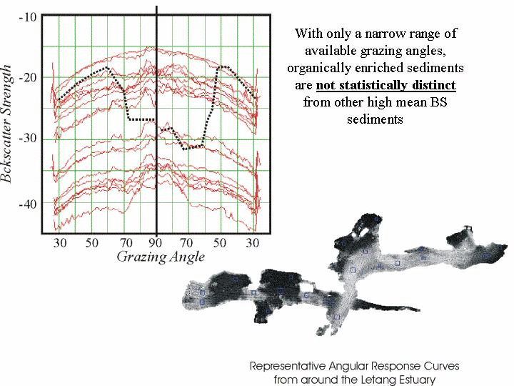 |
Across the whole estuary can see a wide range of average backscatter strength values that clearly include natural sediment with about the same response as the organically enriched sediments. Without access to the full grazing angle variability is is not possible to separate the two. Thus, as in slides above, we can't yet unambiguously distinguish enrichment from other natural phenomena like rougher bottoms.. |
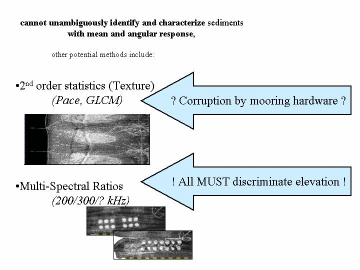 |
Other ways to go are texture but that is complicated by the signature of the mooring hardware ... Or multi-spectral - but every spectral band must have elevation angle distrimination - i..e many multibeams and thus very expensive. |
 |
in conclusion - the two imaging
methods are useful (and a lot more spatially extensive than diver
samples) but are not yet a stand alone method of quantitatively mapping
organic enrichment. A combination of diver sampling, targeted by pattern recognition in the acoustic imaging probably represents the optimal compromise to date. |
Hughes Clarke, J.E., Roy, A. and Reed,
C., 1997, Bay
d'Espoir, Aquaculture Surveys, Overview and Highlights, Simrad EM3000 -
CSS Puffin -Sept 19-22, 1997: http://www.omg.unb.ca/~jhc/bdespoir/HighLights.html
Tlusty, M.F., Hughes Clarke,
J.E., Shaw, J., Pepper, V.A. and
Anderson,
M.R., 2000, Groundtruthing Multibeam Bathymetric Surveys of Finfish
Aquaculture
Sites in the Bay d'Espoir Estuarine Fjord, Newfoundland: Marine
Technology
Society Journal, v.34, no.1,
p.59-67.
Hughes Clarke, J.E., 2001, Remote
Acoustic Characterisation of Mariculture Site Sediments: in Hargrave
and Phillips Eds., Environmental Studies for Sustainable Aquaculture
(ESSA), Canadian Technical Report of
Fisheries and Aquatic Sciences No.
2352.
Hughes Clarke, J.E., Wildish, D. and
Akagi, H., 2002, Monitoring near-field changes at mariculture sites: a
comparison between multibeam and pole-mounted sidescan: in Hargrave,
B.T (Editor). 2002. Environmental Studies for Sustainable Aquaculture
(ESSA): 2002 Workshop Report. Can
Tech. Rep. Fish. Aquat. Sci. 2411: v+
112 pp.
Hughes Clarke, J.E., Wildish, D. and Duxfield, A., 2002, Acoustic Imaging of Salmonid Mariculture Sites: Canadian Hydrographic Conference Proceedings CDROM.
Wildish, D.J., 2004, Acoustic detection of organic enrichment in sediments at a salmon farm is confirmed by independent groundtruthing methods: Marine Ecology Progress Series, v.267, p.99-105